Introduction of the project
In this tutorial, I will demonstrate how to make a project with an RGB LED on a Raspberry PI using D2000 software. First, you need to download an image for Raspberry PI and install it according to the online manual and download the client for Windows. After a successful installation, we are ready to start.
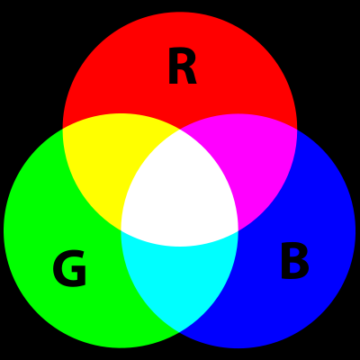
The RGB LED consists of three different LEDs, from the name you can guess that these LEDs are red, green and blue. You could make many colors by mixing up these colors. An RGB LED has 4 pins, 3 pins for each color and a common cathode.
Wiring
For this project we need these components:
1. Raspberry Pi 3
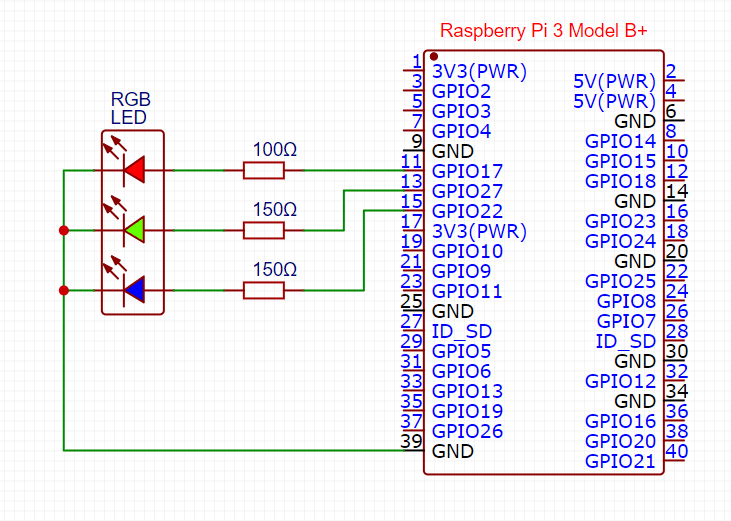
2. Resistors – 2 x 150 Ω and 1 x 100 Ω
3. RGB LED
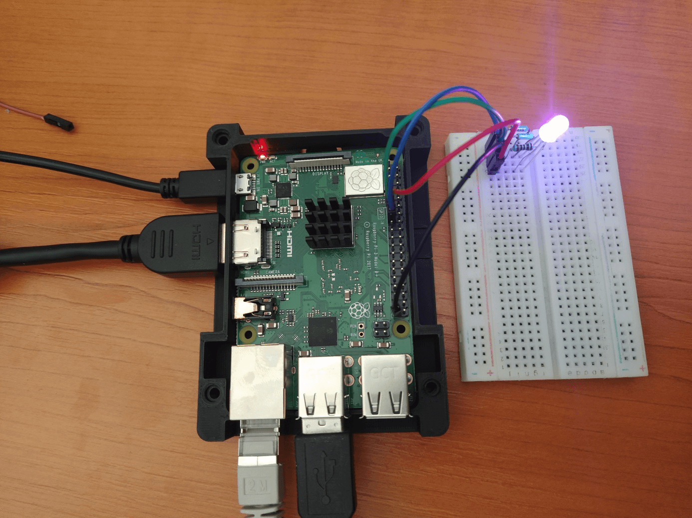
4. Breadboard and jump wires
The cathode will be connected to the ground and the 3 anodes will be connected through resistors to 3 digital pins on the Raspberry that can provide PWM signal.
D2000
D2000 consists of several programs. Three programs are important for common users – GR.EXE, HI.EXE and CNF.EXE:
· GR.EXE (GREDIT) is a graphic editor allowing to create schemes (called pictures) which display the logged technological process.
· HI.EXE (Human Interface - user's console) provides communication of operator with D2000 system. This process displays created schemes contain technological data.
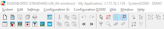
CNF.EXE (CNF) is a process intended to configure various non-graphical D2000 objects (e.g. measured points, historical values, evaluated tags etc). This process is used to create new objects, modify and delete existing ones. It is not necessary open CNF.EXE separate because CNF is now part of GR. You can find it in GR toolbar menu as you can see in the Figure 3.
Picture
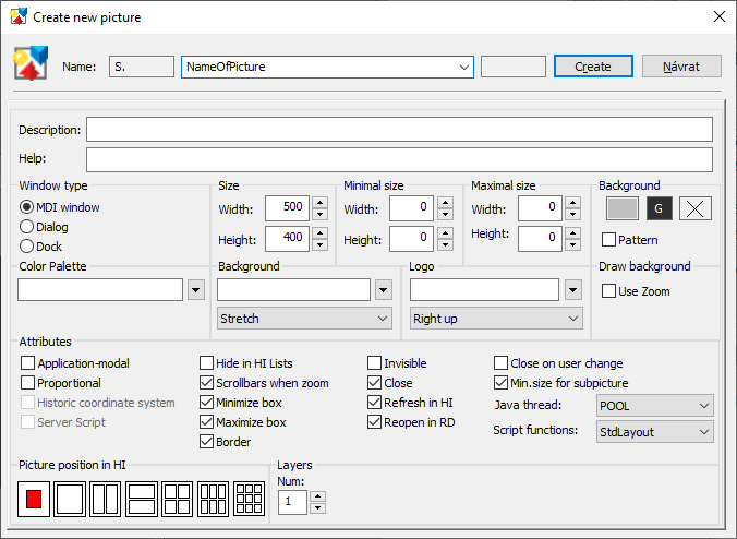
For this project, I decided to make a new picture based on a demo example and I will show you how to make it. First I opened GREDIT application and by clicking on the System button situated in the menu bar and then on New Picture, I created a new picture. I changed the name of the picture to S.LedExample and then finished by clicking the Create button.
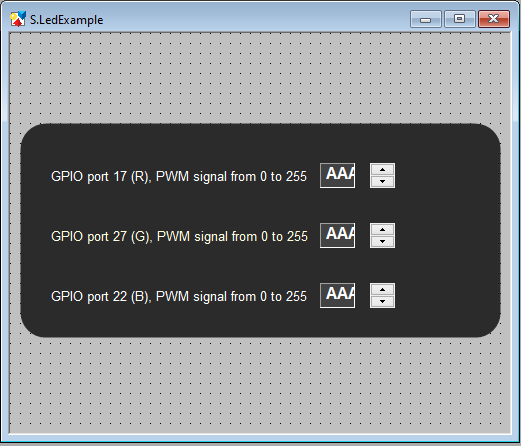
A newly created picture is empty. First, I put a rectangle from toolbars on the left side and used it as a background. On the right side there is the palettes section of component where we can change colors, lines and other visual attributes.
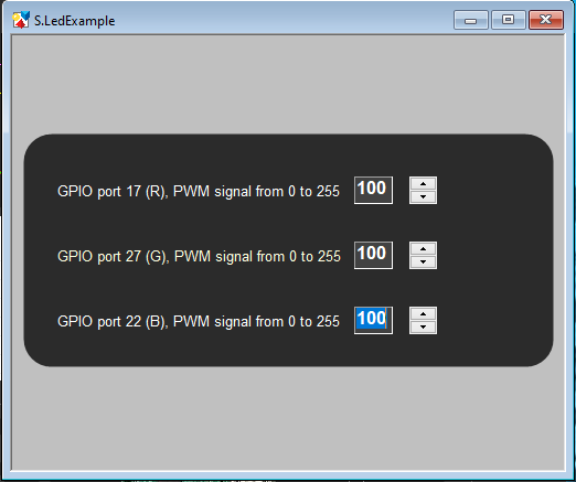
The next step is to create a control panel for the LED. The RGB LED has 3 colors so I need 3 fields for controlling each LED. I used text field for information about the name of pin and additional information about values range sent to GPIO pin. The entry field is used for changing the value of the PWM signal which is controlling the light intensity of RGB LEDs and the spin button can change the value in the entry field. The spin button always changes the value with the step of 1.
New object
If you want make a new object KOM.EXE must be running in background. In Demo project is KOM.EXE launched automatically. KOM is the process of communication and processing of measured values, that allows communication with control systems via serial communication lines.
The entry field has to be connected to the controlled object. A View tab is in the palettes section. There is an entry field for a connected object. After double clicking this field a list of objects is opened. An I/O tag representing the pin 27 was already created as a part of demo program and I needed only to choose it. However, I needed to create I/O tags representing other pins.
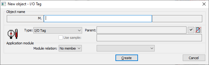
For the Red and Blue colors, I chose pins 17 and 22. For Green LED I am using pin 27 from Demo application. On the top left side there is a button for creating new objects. In this small window (Figure 6), I changed only the name and parent. Parent for newly created I/O tags is existing station B.IRP. After a name is specified, in the next window we can change properties of an object which is being created.
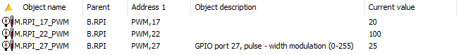
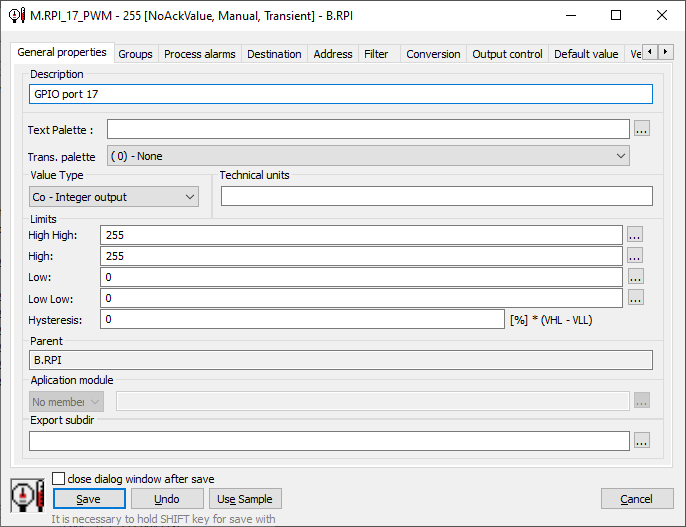
Parameters that I had to change are highlighted In the Figure 8. The value type has to be Co – Integer output and limits are used for maximum and minimum value of PWM signal. On the Address tab there is only one entry field for the tag address of Pin. According to documentation, I used address PWM,17. The same procedure can be used for pin 22, however the address will be PWM,22. Information about pins can be seen in the GPIO protocol documentation.
After all these steps I opened the HI application. When it was running, I closed all open windows from the Demo project and opened my picture (this is possible using CTRL + S shortcut or via menu Open -> Picture, then I selected my new picture S.LedExample).
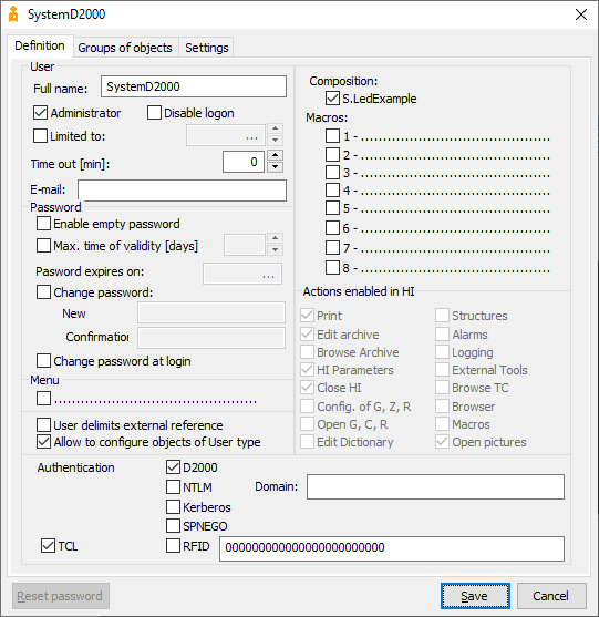
The next step was to have my picture opened automatically after login to HI application. I opened a CNF application, then I chose a User from the list of objects on the left side. Demo application is using preconfigured SystemD2000 user; I changed the Composition to S.LedExample.
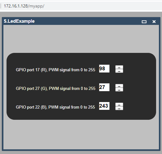
The web interface is available at http: //<raspberry_ip_address>/myapp. In CNF application must be checked if processes for web interface are running. You can find it in object types Process and the running process should be: SELF.SES, SELF.TCD, SELF.TTS and SELF.WSC. If the processes are not running, open the D2000 System Console and look for raspberrypi (my app) in the left pane, join the process and run the mentioned processes, name and password are standard (SystemD2000:SystemD2000). After I checked processes I entered a standard username and password and clicked on the Login button. This way I could access the application without any additional software installed on my computer!
XML Import and Export
XML Import and Export can be started from CNF or GREDIT applications. XML Export is the means to export the object configuration in the form of an XML file. First go to System tab and open XML Export settings and check Recursive export with all referenced objects option. After this from listed object choose All types and write down into Mask text field *name of picture*. Then choose your object and from popup menu activated via right-click click XML Export. XML file will be saved to your chosen folder.
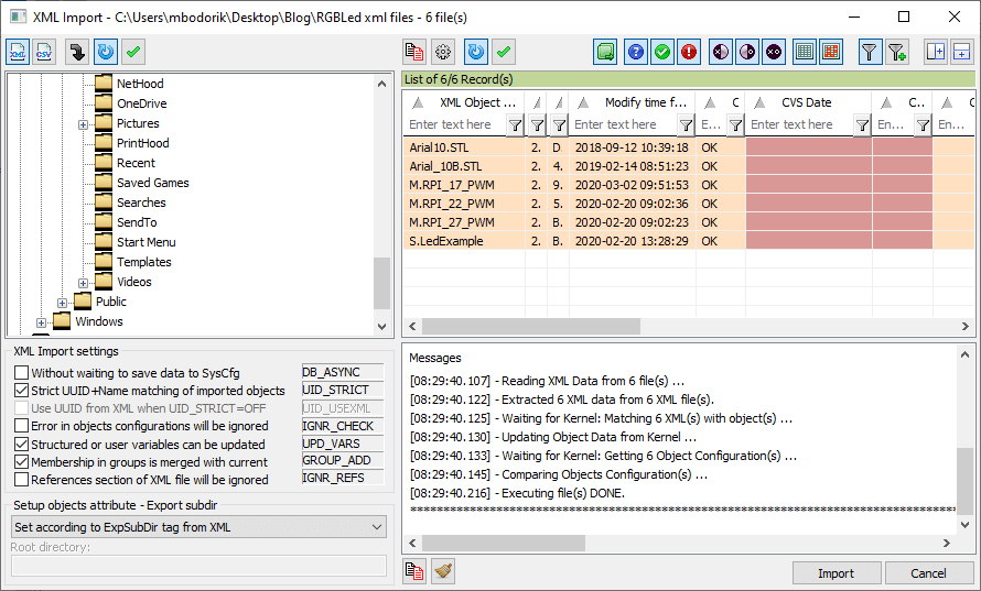
All objects can be exported and if you want to import them on another computer or project. You can download my S.LedExample and import it to your downloaded Demo project. Open XML Import via menu Object -> XML Import in CNF application. A dialog from Figure 11 will open. In the left pane find the folder where XML files are saved and imports all XML objects.
Then open the HI application and open a picture by CTRL + o shortcut. Choose Picture from object types in the left pane and find S.LedExample picture in the main pane.
Conclusion
That was my first experience with the D2000 system. Everything was pretty easy for me. The online documentation doc.ipesoft.com helped me when I had questions. I’m looking forward to further projects with D2000 on Raspberry PI.