Introduction of the project
After the first tutorial, I prepared a project for controlling the DC motor by D2000 software. If you want to make this project on your Raspberry you have to download an image for Raspberry PI and install it according to this online manual and download a client for Windows.
DC is the most common type of motor. DC motors have usually two leads, one positive and one negative. If the leads are connected to the battery, the motor will rotate. The direction of rotation depends on how the leads are connected. If leads are switched, the motor will rotate in the opposite direction.
Wiring
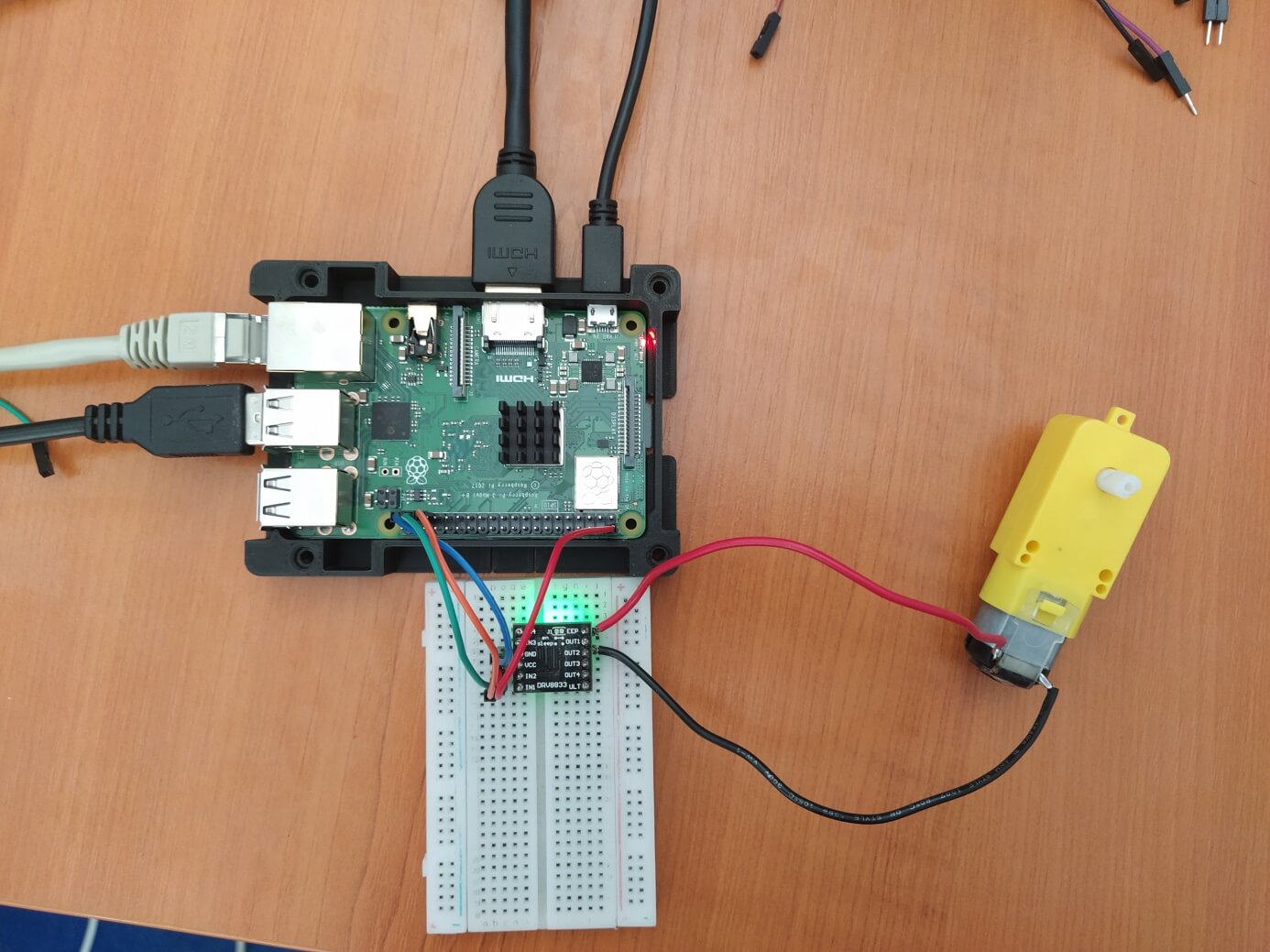
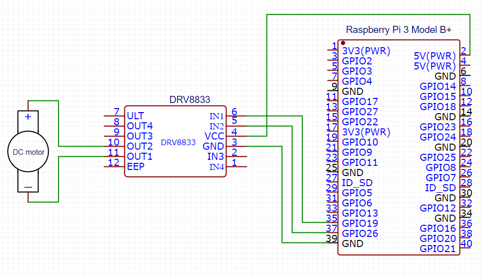
Do not connect the motor directly to the Raspberry pin, this may damage a board. The hardware drivers for DC motor are, for example, DRV8833 or L298N modules. The components which I used are the following:
1. Raspberry Pi 3
2. DRV8833 module
3. DC motor
4. Breadboard and wires
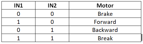
The following table shows which direction the motor will turn based on the digital values of IN1 and IN2.
D2000
For this project, I created a new application to control the direction of the spin of the DC motor by D2000. D2000 consists of several programs. Three programs are important for common users – GR.EXE, HI.EXE and CNF.EXE:
· GR.EXE (GREDIT) is a graphic editor allowing to create schemes (called pictures) which display the logged technological process.
· HI.EXE (Human Interface - user's console) provides communication of operator with D2000 system. This process displays created schemes which contain the technological data.
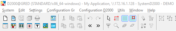
CNF.EXE (CNF) is a process intended to configure various non-graphical D2000 objects (e.g. I/O tags, historical values, evaluated tags, etc.). This process is used to create new objects, modify and delete existing ones. It is not necessary to open CNF.EXE separately because CNF is a part of GREDIT. You can find it in GREDIT toolbar menu as you can see in the Figure 2.
Picture
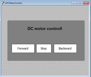
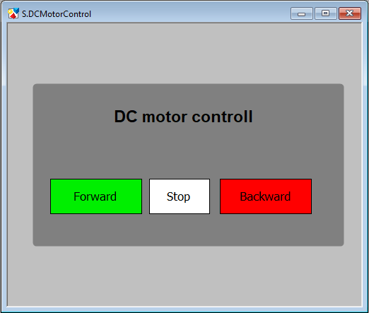
The application design is created in D2000 GREDIT application (Graphic Editor). The first step is creating a New picture by clicking on the System button situated in the menu bar and then on the button New picture. Then just change name and click on Create.
For application design I used a rectangle as a background from toolbar section on the left side. The palettes section offeredvarious colors and features for visible objects. Then I created three buttons for controlling – Forward, Stop and Backward. I chose a text field as a button and put in on workspace. In the palettes section in the Text tab I changed type to the In rectangle and frame to the Frame_background, in View tab make sure that you have connected object in this case I/O pins. I/O tag for pin 26 is already created as a part of the demo project. I had to create an I/O tag for the pin 19. (The procedure is described in the next section).
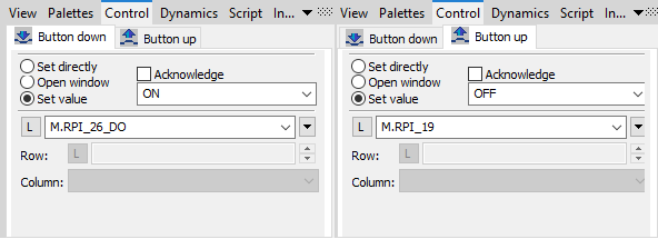
After you have created the object, the next step is logic of control. First, I set up button logic in Control tab. Buttons have the following control logic:
Forward:
o Button down: Set value ON, object to control PIN26 (M.RPI_26_DO)
o Button up: Set value OFF, object to control PIN19 (your new object)
Stop:
o Button down: Set value OFF, object to control PIN26 (M.RPI_26_DO)
o Button up: Set value OFF, object to control PIN19 (your new object)
Backward:
o Button down: Set value ON, object to control PIN19 (your new object)
o Button up: Set value OFF, object to control PIN26 (M.RPI_26_DO)
New objects
If you want to create a new object KOM.EXE must be running in the background. In Demo project, KOM.EXE is launched automatically. KOM is the process of communication and processing of I/O tags, that allows communication with the control systems via serial communication lines.
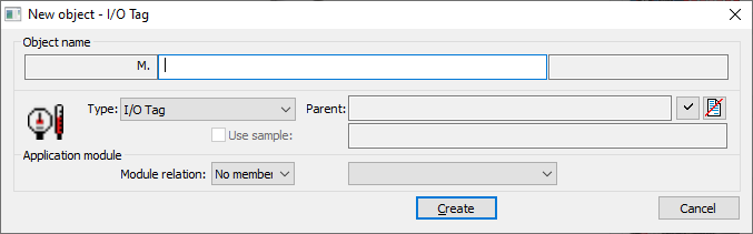
I created a new I/O tag object which will use PIN 19. In the palettes section you can find a View tab. There is an entry field for the connected objects.
On top left side of new window there is a button for creating the new objects. In this window, I changed only the name and parent. Parent for pins what we are going to use is B.IRP. After a name is specified, in the next window we can change properties of the object which is being created.
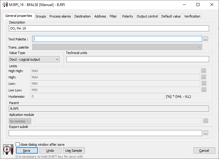
As a description we can use, for example, name of pin, Value type has to be Dout – Logical output. Limits are set automatically and the last parameter that is needed to set is a Tag address in Address tab. According to this documentation the address DO,19is used.
A new palette
The button background changes depending on the direction of rotation. If the motor rotating forward, background of the Forward button is green, otherwise is red. In case the stop button is clicked, values for pins are set to 0 and both buttons are red.
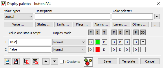
To create a new palette, choose the button. On the right side you can see the palettes section. In the Palettes tab you can see that the first row is empty. By double-clicking the palette menu is opened and in the top left corner you can find the new palette button. Write down the name of it and then choose to create. Now you can see Display palettes, as you can see in Figure 7. I used the Logical value type because the values can be only of two types, 1 and 0 or TRUE and FALSE. For True, the button background will be green and for False, it will be red. After palette is saved you can use it for the second button.
After all these steps I opened the HI application. When it was running, I closed all open windows from the Demo project and opened my picture (you may use CTRL+S shortcut or via menu Open -> Picture), then I selected my new picture S.DCMotorControl.
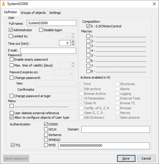
The next step was to have my picture opened automatically after login to HI application. I opened CNF application then I chose a User from the list of objects on the left side. Demo application is using SystemD2000 user. I changed the Composition to S.DCMotorControl.
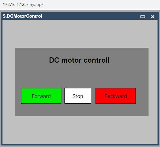
The web interface is available at http: //<raspberry_ip_address>/myapp. I entered a standard username and password (SystemD2000:SystemD2000) and clicked on the Login button. This way I could access the application without any additional software installed on my computer!
In CNF application must be checked if the processes for web interface are running. You can find it in the Process object type and the running processes should be: SELF.SES, SELF.TCD, SELF.TTS and SELF.WSC. If the processes are not running, open the D2000 System Console and look for raspberrypi (my app) in the left pane, join the process and run the mentioned processes, name and password are standard (SystemD2000:SystemD2000).
XML Import and Export
XML Import and Export can be started from CNF or GREDIT applications. XML Export is the means to export the object configuration in the form of an XML file. First go to System tab and open XML Export settings and check Recursive export with all referenced objectsoption. Then choose All types from the listed objects and write down *name of picture* into Mask text field. Then choose your object and from popup menu, activated via right-click, click XML Export. XML file will be saved to your chosen folder.
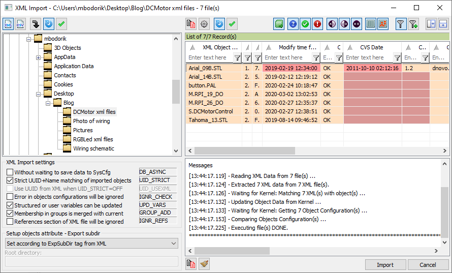
All objects can be exported and if you want to import them on another computer or project you can download my S.DCMotorControl and import it to your downloaded Demo project. Open XML Import via menu Object -> XML Import. A dialog, displayed on Figure 11, will open. In the left pane find the folder where XML files have been saved and import all XML objects.
Then open the HI application and open a picture by CTRL + O shortcut. Choose Picture from object types in the left pane and find S.DCMotorControl picture in the main pane.
Conclusion
After my first try, this project was easier to make than the first one. Everything needed I found in the documentation. I made my own palette for buttons and tried to work with buttons. I hope I will make more of these interesting projects in the future with D2000 software.