
Smart meter devices are becoming a reality and a standard in the energy sector. Legislation that has made a duty from a logical need also requires from Distributor Operators to use the "Intelligent Measurement System" (IMS short). Ipesoft has prepared the second generation of its Ipesoft IMS solutions for distribution system operators, especially with regard to scalability, both for the needs of small as well as large systems.
The first generation of Ipesoft IMS was built on the traditional D2000 KOM communication module. This module is very widely used in various industrial applications. It supports dozens of communication protocols and industry standards and has proven itself in many real-time applications.
However, the DLMS/COSEM protocol contains elements, in particular an archive of measured values integrated in a metering device, which has been modeled too complicated by the traditional configuration cascade line - station - point.
Meet DLMS/COSEM protocol
Check all technical details of the DLMS/COSEM communication protocol in documentation for D2000 SCADA programming platform.
Learn moreIn the case of larger distribution networks, this configuration model has grown considerably and has created increased demands on both human and computating resources. Figure 1 displays data flow when using D2000 KOM.
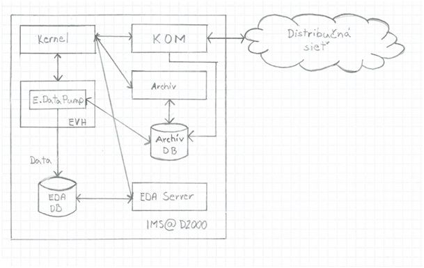
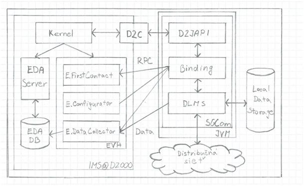
Data collection is carried out according to a defined schedule and the data is temporarily stored in a persistent database. In another schedule they are then forwarded to the central IMS that they communicate with through the Application Program Interface (API). This makes the resulting solution better scalable for small and large distribution networks, has high fault tolerance, while lower demands on human and computing resources. Data flow illustrates the Figure 2.
Ipesoft D2000 SGCom application was developed as a consequence of the need to solve the weaknesses of a traditional solution, specifically in the intelligent measuring devices environment. In the second generation, Ipesoft IMS replaces the original communications core. However, this is a standalone application that, based on the configuration provided, performs data collection from the distribution network. Data collection is carried out according to a defined schedule and the data is temporarily stored in a persistent database. According to another timetable, they are then transferred to the central IMS that they communicate with through the Application Program Interface (API). As a result, the resulting solution is better scalable for both small and large distribution networks, has a high fault tolerance and low demands on human and computational resources. Data flow illustrates Figure 2.
IPESOFT D2000 SGCom
All Ipesoft applications have a distributed client/server architecture that allows scaling the scope of solutions to the needs of a particular deployment, allowing user to get the required power not only logically, but also geographically closer to the place where it is needed, and last but not least it protects critical modules from malfunctions of other parts of the system.
Ipesoft D2000 SGCom is a hybrid application from this point of view. On the one hand, it uses the Ipesoft D2000 Java API (short D2JAPI) application interface through which it communicates with Ipesoft IMS using the Remote Procedure Call (RPC). On the other hand, this connection is used only to accept the configuration and upload the collected data, but it can also work independently, perform the scheduled data collection and store the data locally until it is successfully uploaded.
The application work cycle can be described in the following steps:
- Starting application, reading parameters from the command line.
- Performing local database maintenance - deleting any unwanted artifacts that have remained in the database if the application has been shut down incorrectly. (The local database contains temporarily stored collected data from electrometers.)
- According to the command line parameters, the connection to the central office (typically Ipesoft IMS) is established.
- Receiving the configuration. Exchanging of more RPC is required to receive a new configuration or to modify an existing one. However, the configuration is transferred within the transaction and there is no way that only any part of it may be accidentally applied - it is accepted as a whole lot or nothing at all.
- Establishing the schedule of planned tasks according to the received configuration.
- Regular execution of scheduled tasks:Data collection from electrometers, in parallel, if the connection of electrometers enables it.Transferring data to the central office. The data is released from the local database only after the central office has confirmed to have received data successfully.
- The central office, through the RPC, can enter a command to immediately execute the selected task outside the schedule:Reading any data from the metering device. A typical case is the data recovery from the time period when the metering device was unavailable.Accurate time synchronization in the metering deviceDisconnecting or connecting a selected customer remotely. For example, disconnecting a non-payer until an invoice for energy supply is paid.
- If the connection to the central office is lost, scheduled tasks continue to be performed according to the selected schedule.
Configuration model was designed with two main goals:
- the ability to communicate with smart metering devices across various networks because each of the existing distribution networks is unique and
- the ability to define standardized customers to make adding the new delivery points as well as changing the rules for the existing ones simple.
Communication protocols of physical level
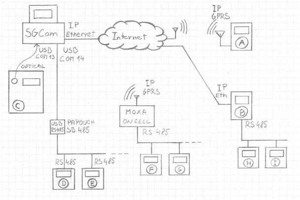
The variety of communication lines that smart meters can be connected to [1] is illustrated in Figure 3. In practice, the following communication interfaces have been supported and tested:
- Optical – an optical head is attached to the measuring device and is held by a magnet. On the computer, the interface appears as a serial port. The figure displays the meter C connected in such way, the optical head is attached to the computer via USB and represented as COM13.
- RS485 serial interface – led out to the terminal block of the meter and/or to the plug-in communication module - depending on the type of device. It can be connected to the meter serial interface meter in several ways.
- IP interface - in the form of an Ethernet port or a GPRS modem. In this case, a "physical" transfer layer is TCP/IP or UDP/IP communication.
[1] The solution was developed especially for the operation of smart electricity meters in electricity distribution network, but the communication protocols used allow also the operation of other types of smart meter devices.
[2] The MOXA device also recognizes the mode, in which the device driver creates a virtual COM port on the computer (e. g. COM15). Practical experience, however, shows that this solution is not reliable enough, therefore the UDP mode was preferred.
Communication Protocols of relational and application level
The communication also differs in that with what kind of higher layer communication protocol the individual smart meter devices communicate and, to a certain extent, it also depends on manufacturer. Ipesoft D2000 SGCom was primarily built for communication using the DLMS/COSEM protocol, while it supports the IEC62056-46 (HDLC) and IEC62056-47 protocols at the relational layer. The IEC62056-21 (IEC61107) protocol is also supported, because experience has required it - some meters that are already in use do not support DLMS/COSEM, or the meter’s owner has deactivated it for the customer.
The IEC62056-47 protocol is used in the ADDAX NP73E electrometer but only when communicating through TCP/IP. Compared to HDLC, it is easier because it does not create relation and does not contain elements of data flow control because it relies on a TCP connection-oriented layer. It is only used to address a specific logical device within one physical device and to specify the client's address, which represents the equivalent of a user account.
The HDLC protocol is used by EMH electrometers, Landis + Gyr, and in case of serial communication even by others. The serial line provides connection-oriented communication, controls and checks the data flow. It is therefore more complex - it includes a mechanism for creating a relation and agreeing on communication parameters. At the same time, it allows addressing a specific physical device on a serial bus where up to 32 devices can be connected theoretically. At the same time, it addresses the logical device within the physical one and also transmits the client's address.
IEC62056-21 protocol is both an application and a relational layer protocol. From the historical and functional point of view, it is a precursor of the DLMS/COSEM protocol and it is considerably easier in terms of implementation. That is why it is supported by almost all types of meters including considerably easier and older devices as well as modern smart meters. On the electrometers from the EMH manufacturer, this protocol has still been a preferred choice so far, amongst other things also because they have introduced different extensions in it beyond the standard. When communicating, the logical devices are not being differentiated and also the address of the client communicating with the device is not stated, the device is addressed as a whole by its serial number.
DLMS/COSEM is in fact not a single protocol but the whole family of standards, superimposed, associated under the IEC62056label. It includes the following parts:
- Object Identification System (OBIS) – IEC62056-61.
- COSEM Object Class Definitions – IEC62056-62.
- DLMS Message Management – IEC62056-52.
- Application layer protocol – IEC62056-51.
- The data is encoded by the standard ASN.1 BER.
Although all of the protocols listed above are standardized, individual manufacturers implement them in their devices with different variations or errors. Ipesoft D2000 SGCom recognizes the types of individual meters and adapts them individually as needed whether it is a specific formatting of HDLC frames, specifying specific parameters of DLMS communications or processing reports that manufacturers have added beyond the standards.
Conclusion
For more than a quarter century, our company has been providing technology solutions and applications in the area of industry and energy. During this time, we have implemented a number of high-end solutions, relying on our technology - the D2000 Real Time Application Server. We believe that its expansion of the D2000 SGCom is another jigsaw element designed for critical applications in the energy sector. To our partners we deliver a solution that can meet the legislative but especially the business requirements that are especially important in this period of "new energy" with a strong emphasis on the ability to know in detail the behavior of customers and suppliers in energy networks, as well as in finding and delivering new products and services associated with energy supply and energy services.
