I had a Simatic S7-300 in my hands and I was curious if I can connect it to the D2000 and see values from the PLC pins and control outputs or write to different memory types in PLC. And the answer is YES.
My Simatic has Ethernet adapter ACCON-NetLink-PRO for TCP/IP communication, so communication is performed using the Ethernet adapter, and I needed only to make an application that will communicate with the PLC. It may seem as an easy task with no work but there are a few steps that allow us to make proper communication.
To start with D2000, you need a running application. First, you have to download the D2000 installation package from D2000 download site and install it as a server. After installation, you have set everything for the new project.
In the installation folder, find d2smc.exe, which is used for creating a new application. When d2smc.exe is started, create a new application by right click on the application and choose the option New application. In the first small window choose PostgreSQL and confirm by OK button.
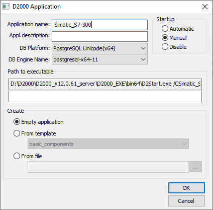
In this second window (what you can see in figure 1) change the Application name for example to Simatic_S7-300. After that, next opened window is D2000 Archive. You may change the parameter but the recommendation is just to confirm with OK button and your application is created. Then you need to start your newly created application. Choose your application and in the left top part of the toolbar there is an icon which runs your application.
When the application is running, open GR.exe, where you can create an application scheme. But first, you have to create a new Line object which allows you to communicate with the PLC. On the top of GR application click the small button CNF to open CNF. In the left pane, navigate to Line.
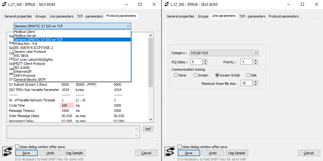
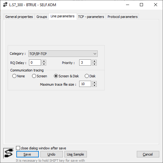
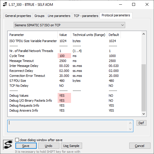
Then create a new Line and configure it. On the "Line parameters" tab, change the category to TCP/IP-TCP and on the "TCP – parameters" tab, change Host to the PLC IP address and change the Port number. The default port for Simatic communication is 102. On "Protocol parameters" tab, in the scroll down list, you have to switch to "Siemens SIMATIC S7 ISO on TCP", so that this protocol’s parameters could be configured.
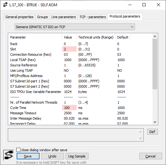
On the "Protocol parameters" tab, at least the Slot and "Cycle Time" parameters must be changed. The most frequently, the correct number for Slot is 2 – which was also in my case. For this specific protocol, you can ignore the Delay parameters on "Time parameters" tab in the Station configuration, as the frequency of polling is controlled by "Cycle Time" parameter in Line protocol parameters (unlike the Delay parameter, the resolution of this parameter is in milliseconds).
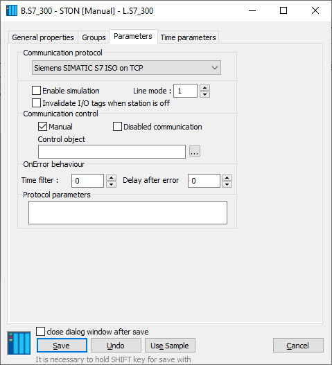
On the left pane navigate to Station and create new Station. As a parent choose previous created Line. On the Parameters tab, you need to change the communication protocol to "Siemens SIMATIC S7 ISO on TCP".
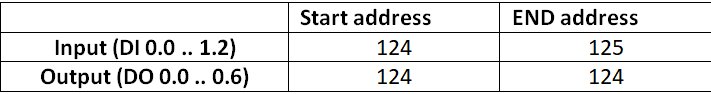
When the Station is configured, you may create new I/O tags for the digital inputs of the device. Their addresses can be obtained from the PLC configuration in TIA Portal. Usually, in the Simatic S7-300 the digital inputs and outputs have these addresses:
Now you can create new I/O tags with these addresses. In the left pane, navigate to I/O Tag and create a new tag with name S7_300_I124.0 which will represent the first Digital Input from the device. In "General properties", change value type to Di – Logical input and in Address set "Tag address" to IX124.0. The address looks weird but it represents more than input offset. The first letter is the specification of block or area in S7 PLC. In the following table you can see the possible values:
The next letter is the data type. In the following table, you can see a few data types but in the online documentation you can find more types.
The number 124 means Digital input address and 0 is a bit which you want to read. The same procedure you can use for Digital output. Digital output address could be QX124.0 and for this address the rules are the same as for the Digital input.
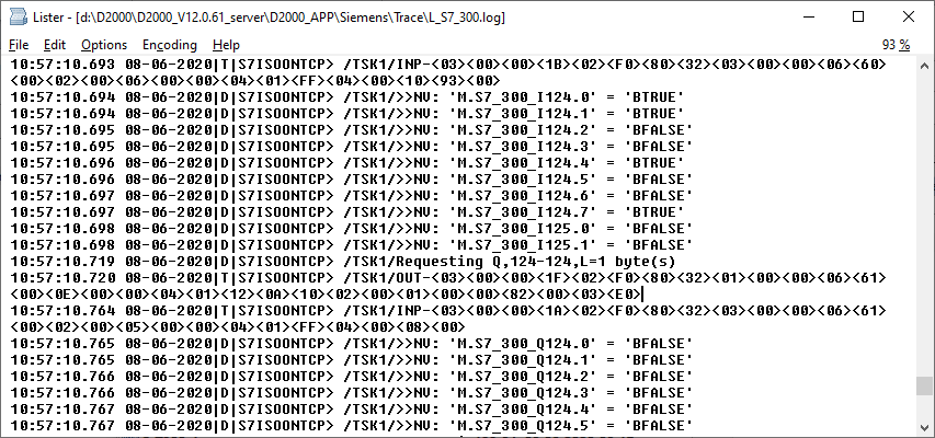
The communication could be checked in the log file but first, enable "Debug session" in Line configuration. On the "Line parameters" tab choose "Screen & Disk" option for the "Communication tracing". Then in "Protocol parameters", you may choose which Debug information you want to see in the log file.
In the log file, which is located in the Trace folder of application directory, you can find the communication logs. As can be seen in a picture below, there is a single data request which covers all Digital inputs and another request which covers all Digital outputs. In these requests, you can see which data are received from PLC (I/O tag names and their respective values).
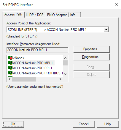
If you want to check PLC configuration, you have to download the PG/PC interface application for ACCON-NetLink from this site. After the successful installation, the proper driver needs to be chosen. Open the application Set PG/PC Interface from your control panel. After the application is opened, you have the choice of drivers according to the interface (PROFIBUS, MPI, PPI). I decided to choose ACCON-NetLink-Pro.MPI.1. In the properties, you have to create a new station where you need a PLC address. For the configuration you could use Step7 or Tia Portal.