
The GPIO protocol is hot news in the D2000 KOM process and has been implemented last summer. How does it work, what does it require and what does it offer?
Platform and requirements
GPIO protocol will be available in D2000 version 12, the release of which is prepared for this autumn. In comparison with the majority of protocols based on serial, TCP or UDP communication that operated on every supported operation system (32-bit and 64-bit Windows, OpenVMS and HPUX), GPIO is available only on one platform. So, which one of the mentioned platforms?
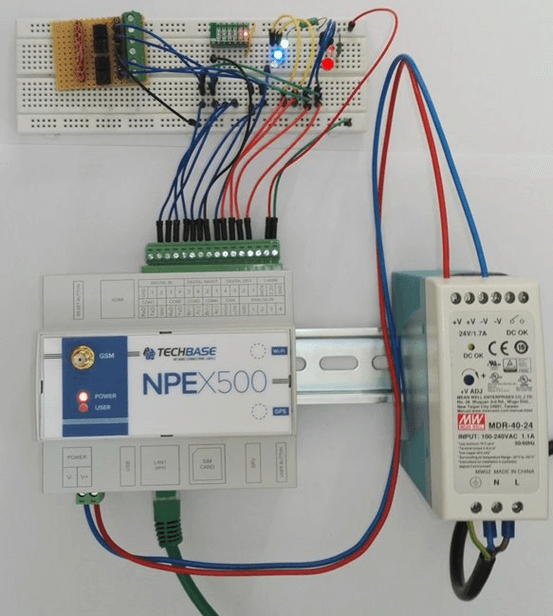
The answer is – on none of them. GPIO protocol enables work with GPIO (general purpose I/O pins) on Raspberry PI computers with I/O computers based on Raspberry PI Compute Module. Today, Techbase NPE X500 is supported, there is possible support of other manufacturers in the future (we can mention the existing industrial computers Sfera Labs Strato Pi and IonoPi, Kunbus Revolution PI or Compulab Industrial Raspberry Pi IoT Computer).
The previous paragraph indirectly suggested that the D2000 version 12 still in preparation was ported on the ARM/Linux architecture, more precisely on Raspberry PI (and compatible computers) to Raspbian operating system. Thus, if your application doesn’t have too high demands and 1 GB RAM and performance of 1.2 GHz of the quad-core processor Raspberry PI 3 (or 1.4 GHz version 3+) is enough, you can use affordable and energetically undemanding ARM computer for your SCADA system. Its memory and CPU should be enough for applications with the extent of hundreds or even thousands of tags.
Functionality
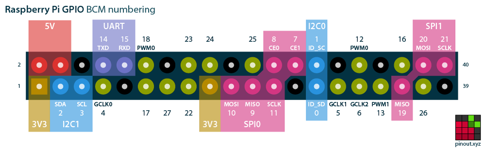
On the Raspberry PI platform, GPIO protocol was implemented with the use of the pigpio library and enables the use of individual GPIO pins for these operations:
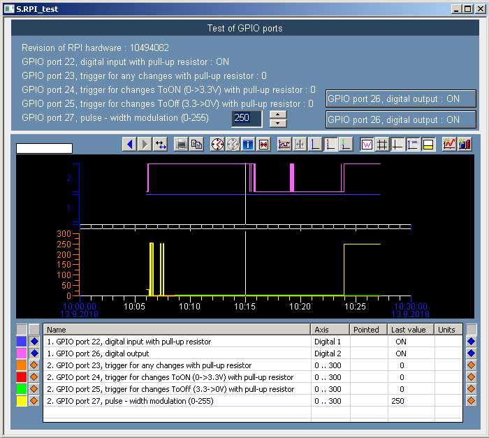
- Reading of digital inputs (input voltage 3.3V corresponds with logical one and 0V corresponds with logical zero). Sampling interval can be configured in parameters of the station (accuracy of seconds) while higher frequencies of sampling can be achieved by setting zero delay and by the configuration of protocol parameter ‘Read Delay Ms’, which inserts delay (in milliseconds) between individual reading cycles.
- Setting values of digital outputs to 3.3V (logical one) or 0V (logical zero).
- Counting of digital signal edges. Counting of rising, falling or any edges is supported. It is also possible to specify time filter – if there is a shorter time interval between two registered events than a defined filter, the second event is ignored and won’t cause an increase of counter value. The time filter is specified in microseconds and the used pigpio library performs the sampling in 5 µs intervals.
- Setting the digital output as a pulse-width modulation output (PWM) enables to control the intensity of connected LED diode, for example.
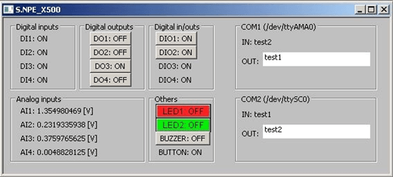
On the Techbase NPE X500 platform, the GPIO protocol was implemented with the use of x1000gpio library from Techbase manufacturer. Unlike Raspberry PI, this industrial computer contains analog inputs (0-10V), digital inputs (0-3.3V), digital outputs of open collector type, relay outputs, two user controlled LED diodes (green/red), a buzzer and a user button. The particular number of individual inputs and outputs depends on the chosen configuration. The GPIO protocol enables:
- Reading values of digital inputs (the input disconnected from the ground corresponds to logical one and the input connected to the ground corresponds to logical zero).
- Setting values of digital outputs – logical one opens the collector and connects the output to the ground.
- Setting values of relay outputs.
- Reading values of analog inputs (0-10V voltage corresponds to values 0-4095 while reading of one input takes about 20ms).
- Setting and detecting the status of the LED diodes.
- Controlling the buzzer.
- Detecting the status of user button.
Conclusion
The GPIO protocol is for the communication with inputs and outputs of Raspberry PI and NPE X500 computer. Present functionality of the protocol can be enhanced in the future (e.g. the possibility of setting sampling frequency and other functions which pigpio library supports). Similarly, if needed, the protocol can be enhanced to support also other industrial computers based on Raspberry PI. Thus, it enables creating a distant KOM server (if needed with the use of KOM Archive functionality), or else embedded SCADA solutions based on the ARM computer.
