
Do you know this communication protocol?
If you work in the field of protections, substations, transformer stations and the like, you will surely answer yes.
And you also know that this is a very complex standard that describes not only communication, but also the object model and naming conventions of objects and their attributes that the IEC-61850 communication protocol transmits. Its intention is to replace proprietary communication protocols (e.g. ABB SPA-Bus or ABB SRIO X3.28), to maximally unify protection devices and substations and enhance their interoperability.
About the protocol
IEC 61850 is an international standard defining communication protocols for intelligent electronic devices (IEDs) at electrical substations. The abstract data model defined in IEC 61850 can be mapped to several protocols. One of them is the Manufacturing Message Specification (MMS), which is another international standard (ISO 9506) for the transmission of real-time process data and control information between devices or computer applications connected to a network. This method is also used to transfer information between the IED and the higher-level SCADA system, where communication takes place over a TCP connection - so a TCP/IP-TCP line is used on the D2000 side.
Another mapping is the so-called GOOSE (Generic Object Oriented Substation Events) and GSSE (Generic Substation State Events) messages. These are built directly on Ethernet frames (without using TCP/UDP) using VLAN tagging and quality (IEEE 802.1Q) and are mainly used for real-time communication between protections. This method of communication is not supported in the D2000 KOM process.
What may be interesting for D2000 users, the MMS protocol is also used by another communication protocol, namely ICCP/TASE-2 (IEC 60870-6). This fact greatly helped the implementation of the IEC 61850 protocol, as it was enough to expand and supplement the existing MMS implementation with the necessary messages and structures.
ASN-1 is used to describe MMS messages and BER (Basic Encoding Rules) binary encoding defined in ISO/IEC 8824-1 and ISO/IEC 8824-1 is used for their transmission. Thus, all logs from the D2000 KOM process in this blog show only the textual representation of the MMS messages after they have been parsed.
Unlike ICCP/TASE-2, the IEC 61850 protocol defines a wide range of basic data types (Boolean, Float32, Float64, Integer8, Integer16, Integer32, Integer64, Unsigned8, Unsigned16, Unsigned24, Unsigned32, VisibleString, OctetString, MmsString, UnicodeString, BitString, UtcTime, TimeOfDay) and makes it possible to create arrays and structures (also multi-level) from these basic types and use them to describe a defined object model - in a very similar way to how arrays and structures are used, e.g. in C or Ada.
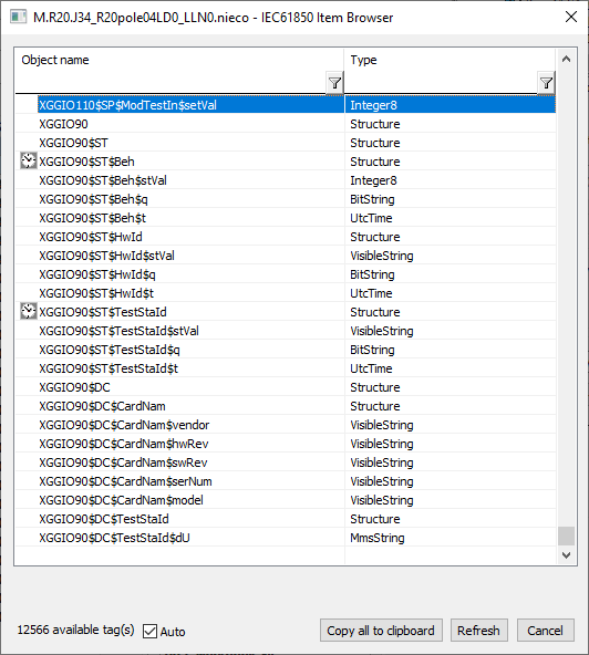
The following figure shows a small part of the objects browsed from a specific protection device ABB REF 614 (in the lower part of the figure there is information about more than 12 thousand objects and attributes). Specifically, the XGGIO90 object (structure) is shown with its ST (XGGIO90$ST) and DC (XGGIO90$DC) attributes - note that the delimiter is a dollar sign instead of the usual dot. Both of these items are in turn structures and contain other items, e.g. Beh is a structure with items stVal of type Integer8 (object value), q of type BitString (quality) and t of type UtcTime (time stamp).
Object values can be obtained from communication in two ways:
• from information reports
• by periodic polling
Information reports
The IEC 61850 protocol defines the so-called buffered and unbuffered reports.
The report contains the values of defined objects and is generated at various events (according to the setting of the Report Trigger Options protocol parameter) - e.g. a change of value, a change of quality, or regularly (so-called integrity report). The definition of the report and the inclusion of objects in it is a matter of the IED configuration, so the D2000 KOM process only activates and uses the reports.
The difference between buffered reports and non-buffered ones is that when communication is lost, the IED stores (buffers) the changed values and then sends them to the SCADA system after communication is restored.
Retrieving object values from reports is the preferred and recommended way of communicating with IED.
How does working with reports work from the point of view of the D2000 KOM process?
After communication has been established, a request to read the details of the report follows. The request contains the logical device name mapped to the MMS domain name. Each IED can contain several logical devices - e.g. ABB REF 615 protection device includes:
• Control logical device – CTRL
• Disturbance recorder logical device – DR
• Protection logical device – LD0
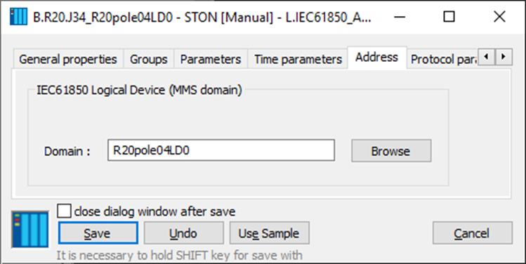
Each logical device whose values we need to read is mapped to one object of the Station type in D2000 (station address is the name of the logical device).
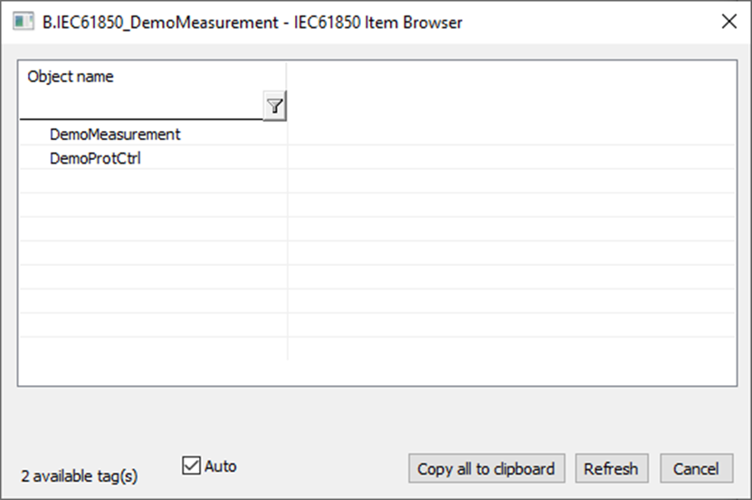
D2000 supports browsing the list of logical devices, so when configuring a Station type object, it is possible to open a dialog with the "Browse" button, to which the D2000 KOM process will send a list of received logical devices.
This completes the configuration of the station, usually nothing more needs to be set.
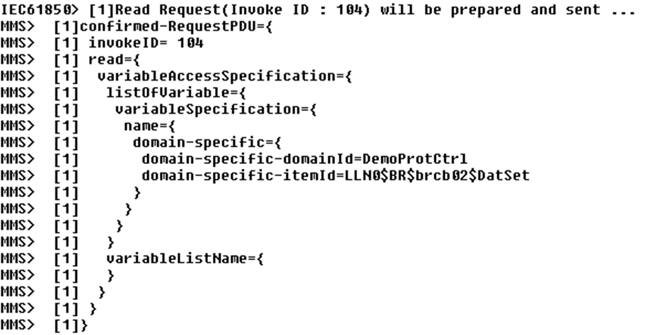
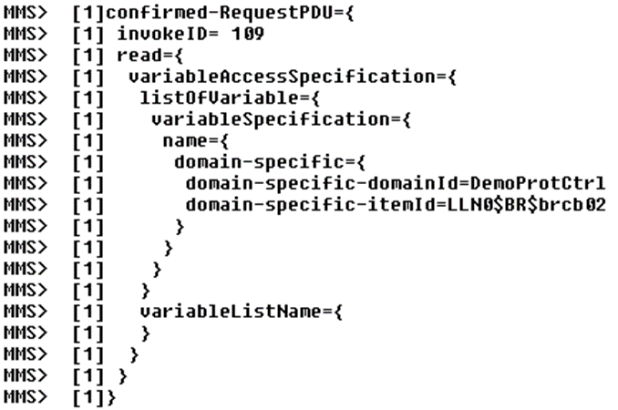
The following figure shows a request to read the buffered report dataset of the DemoProtCtrl logical device. A dataset is a list of objects that the report contains. Note that the name of the read dataset is composed from the name of the logical node (LLN0), from the information that it is a buffered report (BR), from the information about the name of the specific report (brcb02) and finally from the specification of the name of the attribute - the name of the dataset (DatSet). Individual elements of the name are again separated by a dollar sign ($).
The IED responds with a message containing the definition of the requested Dataset name.
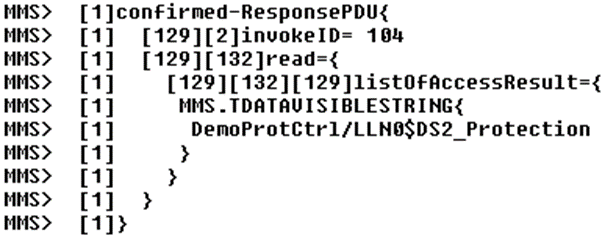
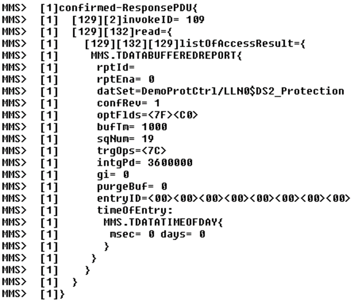
Then follows the reading of the control block of the buffered report (brcb):
In response, the IED sends a definition of the control block, which contains information on whether the report is active and what its other parameters are (integrity period, trigger options and others).
Note: the definition of the control block of the unbuffered report is different - it does not contain items purgeBuf, entryID, timeOfEntryand optional item resvTms).
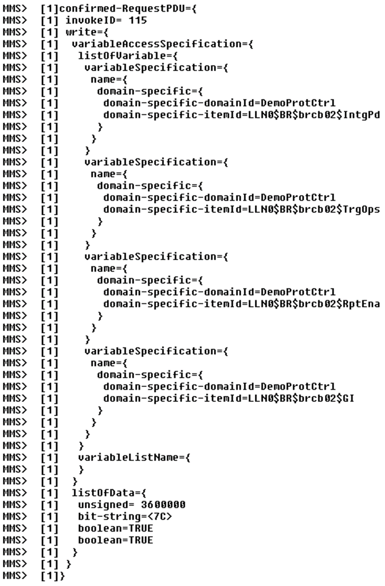
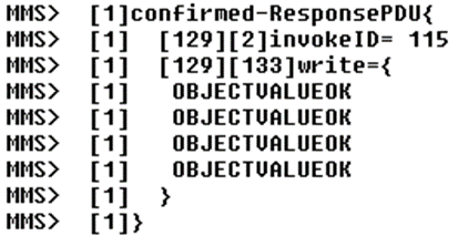
This is followed by writing to the four attributes of the control block, which activates the report. The attributes Integrity Period (IntgPd), Trigger Options (TrgOps), Report Enable (RptEna) and General Interrogation (GI) are written to. In the D2000 configuration, one configured I/O tag (of Buffered/Unbuffered report type) corresponds to each report that we want to activate. The value of the Integrity Period parameter is in the configuration of the I/O tag and is defined as the number of milliseconds after which the IED will generate a report with the values of all objects (for integrity reasons – if there is a loss of data from some change reports). The value of the Trigger Options parameter is defined as a station parameter – Report Trigger Options – indicating which events the report is to be generated. The values of the Report Enable and General Interrogation parameters are always True - so that the report is activated and the IED immediately sends a complete report with the values of all objects.
The IED responds by confirming that the writeing into the control block was successful and the report is therefore activated:
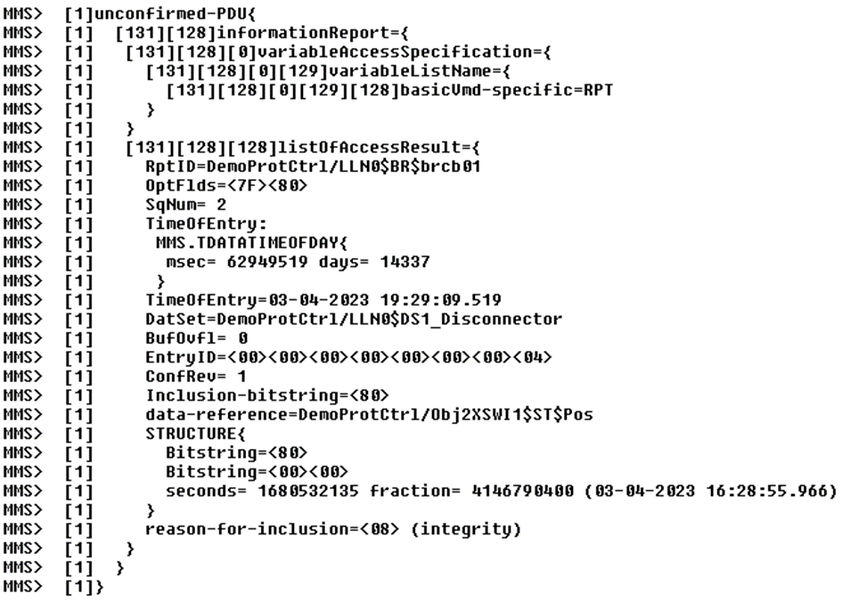
And since we wrote the value TRUE in the GI attribute, an integrity report immediately follows:
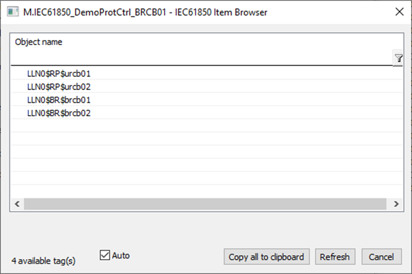
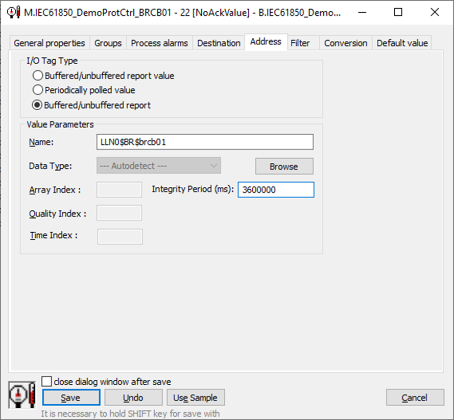
How do we configure the I/O tag corresponding to the report? If the communication with the IED is functional, similarly to the case of the station, we can use the "Browse" button to open the list of reports that the D2000 KOM process reads from the IED.
In addition to the name of the report, it is also possible to enter a period (in milliseconds) with which integrity reports will be generated.
There can be several reports within the logical device, but D2000 KOM activates only those configured in the I/O tags of the Buffered/unbuffered report type.
If such an I/O tag has an integer value type, it will acquire the following values:
• 0 - after establishing communication - after sending a request to read the Dataset name
• 1 - after reading the Dataset name
• 2 - after reading the report parameters
• 3 - after reading the objects contained in the Dataset
• 4 - after successful activation of the report by writing
• 5 and more - with the arrival of each additional Information report, the value will increase.
• invalid – if one of the communication steps fails
This can be used e.g. for defining application watchdogs and for reporting problems when the value of such an I/O tag does not change over time.
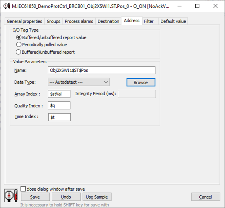
The I/O tags that are part of the report are similarly easily configured. The Type is set to Buffered/unbuffered report value and then the „Browse“ button is used to displays a dialog containing all the objects that are part of the report. Some have icons with them - that is, if the quality ($a) and time stamp ($t) items are also part of the structure.
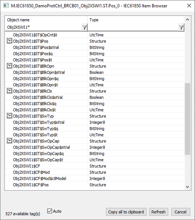
After browsing such a variable, in addition to the Name item, the Array Index, Quality Index and Time Index items are filled in with the attribute names. In older versions of D2000, only numeric indexes (the order of the attribute in the list relative to Name) were supported. The Array Index item can also be used to specify the index of an element within an array (hence its name). Arrays and structure items are indexed from 0. To access any element within nested structures, the index can also be entered in a complex format, e.g. 0.3.1 (the 0th element within the highest array/structure, then the 3rd element in the nested structure/array and the 1st element in the next level of nesting).
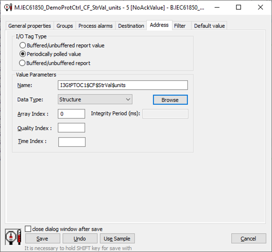
Periodic polling
This is periodic polling of the IED using Read-Request messages, to which the device responds with Read-Response messages. The disadvantage of such a method of communication is, on the one hand, burdening the IED with periodic communication and, on the other hand, the possibility of data loss between individual requests – if some value changes quickly several times, periodic reading usually does not capture all the changes. But some objects are not part of the reports, so there is no other option.
The configuration of the I/O tags is almost identical to the the I/O tags that are part of the report. The difference is only in the type of the I/O tag, which must be set to Periodically polled value. If the object is a structure/array, again attribute names or indexes can be specified.
Conclusion
IEC-61850 is an open comprehensive standard for communication with devices (protections, transformers and others) within electrical substations. It is currently being deployed as a replacement for proprietary protocols of several manufacturers. We already have it deployed on several applications today, other uses are in the preparation stage, and some of our OEM partners have also shown interest. Therefore, we assume that this protocol will be used more and more often in energy applications built on the Ipesoft D2000 real-time application server.
April 6, 2023, Ing. Peter Humaj, www.ipesoft.com
