After a successful testing of the Unipi Neuron L203, I got my hands on another Unipi device. It is called Unipi Patron S107 .
The main difference between the Neuron device from my last blog and Patron is the CPU, Neuron uses a Raspberry Pi 3 Model B CPU, on the other side Patron is based on Unipi Zulu ARM x64 industrial computer. The next difference is in memory. Instead of a microSD card, Patron has eMMC onboard memory.
First, it is necessary to enable SSH via a service web interface. In the Unipi package, there is a leaflet with instructions about how to enable SSH and connect to the Unipi via SSH client.
Every Patron comes with a pre-installed OS based on Debian with Unipi drivers, for example Modbus TCP server or SysFS. First, we need to download a D2000 installer for ARM Linux (this D2000 installer version is available upon request) and copy it to the Unipi. When I unzipped the installer, I ran a ./doinstall scrip which installed D2000 on the Unipi.
Before D2000 is used, it is necessary to install the PostgreSQL database and PostgreSQL odbc driver:
1. To install the PostgreSQL server, run:
sudo yum install postgresql-server postgresql-contrib
2. To initialize the database, run:
sudo postgresql-setup initdb
3. To start PostgreSQL, run:
sudo systemctl start postgresql
4. Turn on automatic PostgreSQL startup after OS startup:
sudo systemctl enable postgresql
5. To install the PostgreSQL ODBC driver, run:
sudo yum install postgresql-odbc
Because of the x64 ARM processor, D2000 is missing some libraries which have to be downloaded by the user. They are:
1. unixodbc:armhf
2. libuuid1:armhf
3. odbc-postgresql:armhf
4. zlib1g:armhf
When the libraries were updated, I created a new user by the command adduser <username>. Later, during the installation, I used the created user with whose rights the D2000 will run. The d2app script is located in the /opt/d2000/bin folder. The attribute script shows available attributes that could be used to create, start, or delete the application.
By command ./d2app create an application can be created and then by command ./d2app start application_name application can be started. The command ./d2app also has a parameter auto-start that starts the application when the device is started.
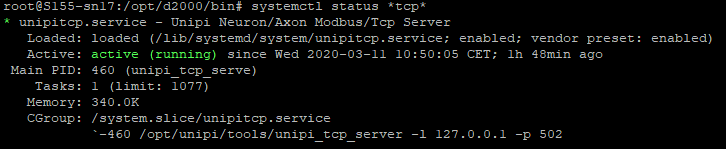
How I mentioned Patron s107 has a pre-installed Modbus TCP which starts when the device is booting. It can be checked by the systemctl status tcp command. In the following picture, you can see which IP address and port are used by Modbus.
D2000 Modbus configuration
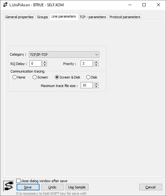
When the application is running on the PLC, the next step is to establish communication between the PLC and the D2000. First I created a new object “Line”. Now we need to change something in the Line Parameters tab of the dialog window. Change the Category to TCP/IP-TCP, because Modbus on Patron communicates via TCP. In the Line parameters tab, there is also the Communication tracing option which is responsible for tracing the communication with the communication line. There are 4 options for tracing:
· None – no outputs;
· Screen - diagnostic outputs are displayed only on the screen;
· Screen & Disk - diagnostic outputs are displayed on the screen and they are saved in the LINE_name.LOG. file which is located in the Trace folder of the application directory;
· Disk - diagnostic outputs are saved only into a LINE_name.LOG file.
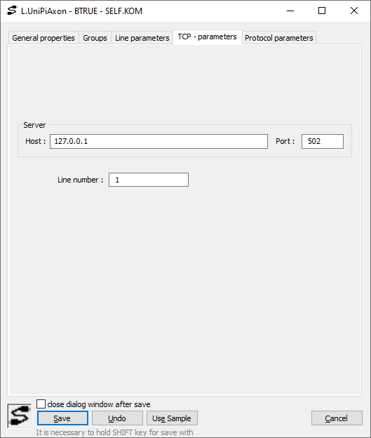
In the TCP – parameters tab, there is a field for host and port specification. The IP address and port can be found in the last line of Figure 2. The IP address in Figure 2 represents a loopback IP address and it must be used as a host. The Line number is not used, so we can set it to for example “1”.
The next part of communication is the Station which represents the logically or physically bounded groups of tags (objects of I/O Tag type), for which the communication process acquires current values. In the Station dialog window, there is the Parameters tab, where the communication protocol must be configured, in this case, it will be the Modbus Client.
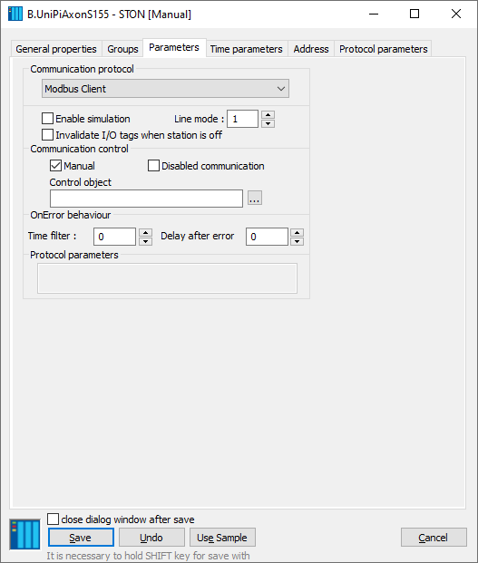
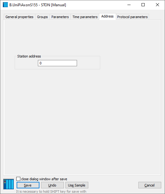
Stations represent the PLC units, Unipi Patron S107 has only one unit but the D2000 could access peripherals via two station addresses according to the Modbus map of Patron S107. These stations are:
· Unit 0 which represents broadcast;
· Unit 1 is the first and only unit of the Unipi Patron S107.
I/O tags addressing
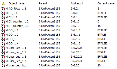
After Line and Station are configured, it is time to create the I/O tags. The Peripheral addresses are in the Modbus map of the device. In the following picture, you can see the Modbus address. It may seem complicated, but in reality, it isn’t.

Examples of address configuration for Unipi Patron S107:
· 3.0.1 - a 16-bit signed number is read by the function Read Holding Registers from the address 0 as a 1st bit in a byte which represents the digital input 1,,
· 3-6.20.0 – a 16-bit signed number is read by the function Read Holding Registers as a 0th bit from address 20 and is written by the function Write Single Register which representing User Led 1.
· 3-6.2 - a 16-bit signed number is read by the function Read Holding Registers from address 2 and is written by the function Write Single Register which represents the Analog output raw value.
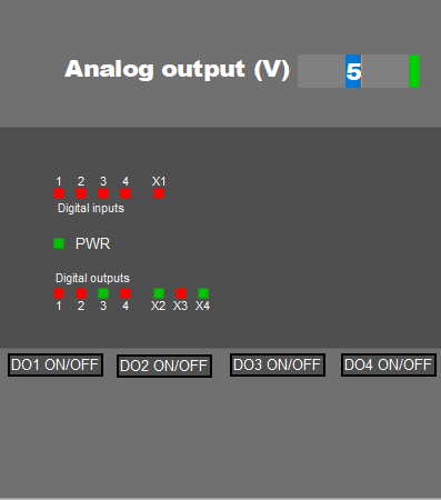
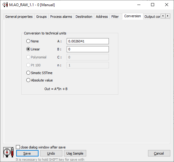
According to the documentation, the maximal value of the analog output could be 10V, but the raw value could be different. I measured output voltage on the analog output and tried to find the maximal raw value. I found the maximal value 3840 and I wanted to change the output value to a voltage (from 0 to 10). Every object has a Conversion tab which can be found in the I/O tag dialog window. The correct way to convert these values is a Linear conversion in the form of out = A*In + B. So I had a system of linear equations with two variables in the following form:
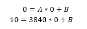
From this linear system I got a result: A = 0.0026041 and B = 0. I inserted these two variables in the Conversion tab and now the analog output raw value represents voltage.
Conclusion
After Line and Station are configured and I/O tags are created D2000 can communicate with the Unipi Patron and read/write to Patron S107 I/O tags. I hope that this manual did give you all the necessary info on how to combine the D2000 platform and the Unipi Patron device. By combining these two technologies, you can create a device with a vast array of possible utilizations. Soon we will bring you a case study describing how we used this combination and also how it could be potentially used to create an effective IoT edge device. So don’t hesitate and try to explore all the possibilities brought by combining the D2000 and the Unipi devices.