
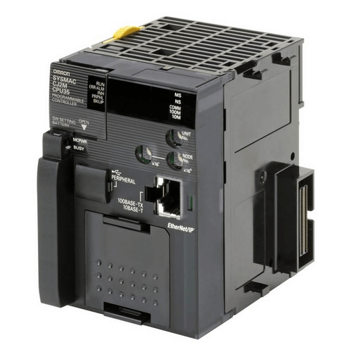
The Omron FINS (Factory Interface Network Service) protocol is a proprietary standard developed by the Omron company for the communication with their PLCs over an Ethernet network.
Communication with the Omron PLCs is now possible with the D2000. The list of supported protocols keeps growing.
Unlike other proprietary communication protocols (e.g. Simatic S7), this protocol is documented and therefore its implementation is relatively simple.
Medium
The FINS protocol has two variants: the FINS/UDP protocol uses UDP packets for communication, the FINS/TCP protocol uses TCP connections.
When to use which? When it comes to communication in a simple network environment, we recommend the FINS/UDP variant. If the network is complicated - including firewalls, NATs, and other ‘delicacies’ that work better with TCP connections than with UDP datagrams - we recommend the FINS/TCP variant (if it is supported by a specific PLC model). Its disadvantage is larger amount of transmitted data - each request and response is wrapped in a 16-byte envelope. In addition, an initial "handshaking" takes place during the connection establishment, during which both parties exchange several communication parameters.
When implementing the FINS protocol, we first implemented support for the basic FINS/UDP variant and later added support for FINS/TCP.
The default port number on which Omron PLC operates is 9600 for both variants.
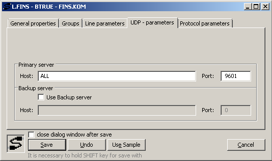
If we want to use the FINS/UDP variant, then on the D2000 side we must use the TCP/IP-UDP category line and set the interface and port number from which the D2000 KOM process will send requests and on which it will expect responses. The port can be 9600, but also any other.
In the case of the FINS/TCP variant, a line of the TCP/IP-TCP category is used. Since we wanted to maintain the compatibility of the configuration with the UDP variant, where the IP address of the PLC is located on the station, the configuration parameters of the TCP/IP-TCP line (IP address, port, line number) will not be used for communication (they can be set to arbitrary values).
Station
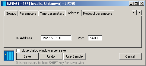
Each PLC corresponds to one Station type object in the D2000. As part of the configuration, it is necessary to enter the PLC IP address and port number.
The Omron FINS protocol supports not only communication with a directly connected PLC, but also routing to other networks that are connected to the PLC and those that do not have to be based on the Ethernet standard. It is possible to communicate with PLCs in Ethernet, Host Link, Controller Link, SYSMAC LINK, SYSMACWAY and Toolbus networks.
A PLC connected to an Ethernet network that communicates directly via a TCP connection or UDP packets with the D2000 KOM process is called a gateway PLC. The PLC with which we want to communicate is called the target PLC.
So - how can we address such PLCs? Plus, when the address in each type of network can be different?
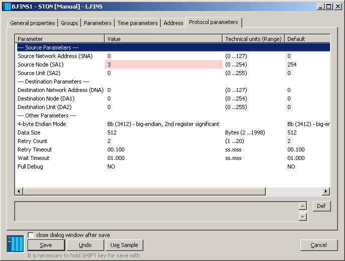
The Omron FINS addresses these issues by introducing 1-byte fields in the protocol header that specify the network, node, and unit addresses — for both source and destination. A value of 0 means "this node" (or this unit) by default. Each gateway PLC contains tables with the configuration of individual networks to know where to forward a request or response that is not intended for the gateway PLC. Six protocol parameters (3 in the Source Parameters group and 3 in the Destination Parameters group) are used to configure these parameters in the D2000.
Special attention should be paid to the Source Node parameter. Of course, a value of 0 is not suitable, as the communication source is a computer with a D2000 KOM process and not a local PLC. During testing, we found that values of 3 and higher are functional (probably related to existing nodes on the network). In some cases (depending on the PLC settings) the Source Node parameter must be set to the last part of the computer's IP address (e.g. for address 192.168.0.10, the value is 10).
For the FINS/TCP variant, on the other hand, a value of 0 is recommended (if communicating directly, without using a gateway PLC). A value of 0 means that the PLC assigns both the Source Node value and the Destination Node during the initial "handshaking" when establishing a TCP connection (so the configured value of the Destination Node parameter is not used).
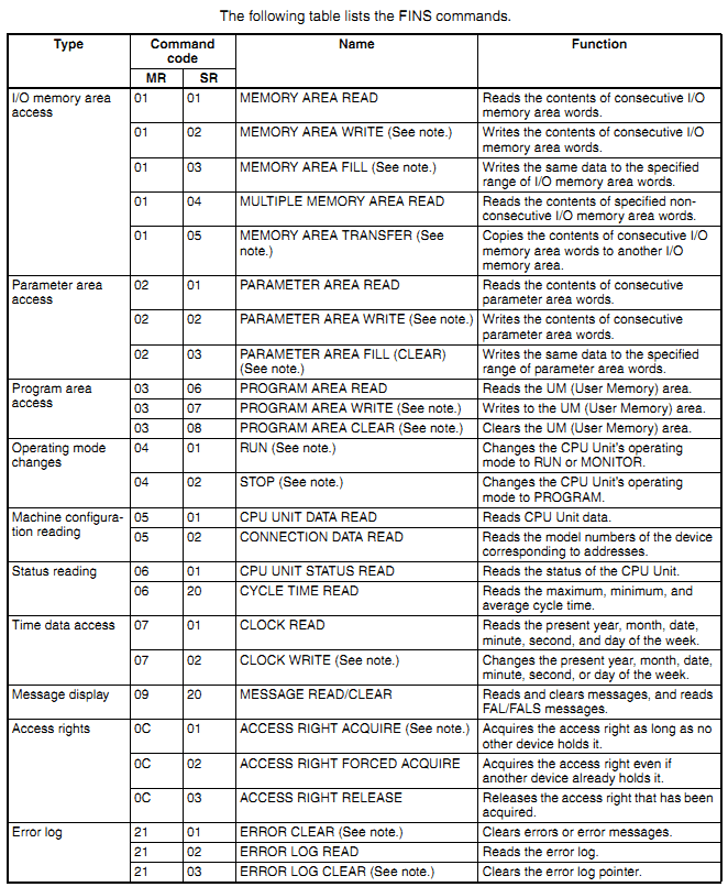
Services
When reading and writing variables in the D2000, we were satisfied with two basic commands - MEMORY AREA READ and MEMORY AREA WRITE. These allow you to read a contiguous region of memory. There is also the MULTIPLE MEMORY AREA READ command, which allows reading multiple cells (in element protocol terminology) from different addresses of the same memory type. We haven't supported this addressing yet. On the other hand, the aggregation of readings of values of several measured points (we call them I/O tags) by a single command is supported. The maximum size of the read data is specified by the Data Size protocol parameter.
Data model
The data model of the Omron FINS protocol is similar to the Modbus protocol. There are several types of memory (not just "registers" and "coils" like in Modbus). Each memory type has a 16-bit byte address and a 1-byte bit address. It depends on the specific type of device, how large its addressable area is.
A memory unit located at a specific address is called an element. Some types of memory can be addressable by bit or byte. The D2000 currently supports byte addressing of the following memory types:
· AR - Auxiliary Area
· DM - DM Area
· CIO - CIO Area (external inputs/outputs)
· HR - Holding Area (persistent values that survive PLC shutdown or program stop)
· TC - Timer/Counter Area
· WR - Work Area (memory for programming)
All of these types have 2-byte elements (similar to registers in the Modbus protocol).
Addressing
What does the address of the I/O tag look like?
It contains the type of memory and then the address of the element (e.g. DM025). The address can also be entered in hexadecimal using the hash character - ‘#’), e.g. AR#1B. Optionally, it is possible to enter a bit number (0-15) if it is necessary to address a specific bit, e.g. HR00200.0. Finally, you can specify the type of data - the way the data will be interpreted:
|
Type |
Description |
|
BIT |
Single bit operation
(default value if the address contains a bit specification, e.g. HR1.3) |
|
BYTE_U |
The upper (first) byte of
the registry |
|
BYTE_L |
The lower (second) byte of
the register |
|
WORD |
Register interpreted as a 16-bit unsigned number (default
value if the address does not contain a bit specification, e.g. HR1) |
|
SHORT |
Register interpreted as a
16-bit signed number |
|
BCD |
Register interpreted as
unsigned BCD number (0-9999). |
|
SBCD |
Register interpreted as a a
signed BCD number (+/- 7999). The highest bit defines the sign. |
|
LBCD |
Two 16-bit registers
interpreted as a 4-byte unsigned BCD number (0-99999999). |
|
SLBCD |
Two 16-bit registers
interpreted as a 4-byte signed BCD number (+/- 79999999). The highest bit
defines the sign. |
|
DWORD |
Two 16-bit registers
interpreted as a 32-bit unsigned number (the byte order depends on the 4-byte
Endian Mode parameter) |
|
LONG |
Two 16-bit registers
interpreted as a 32-bit signed number (the byte order depends on the 4-byte
Endian Mode parameter) |
|
FLOAT |
Two 16-bit registers
interpreted as a 32-bit floating-point number (the byte order depends on the 4-byte
Endian Mode parameter) |
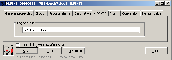
Here are some examples of I/O tag addresses:
· DM00020, FLOAT - elements 20 and 21 of the DM area interpreted as a 32-bit floating-point number
· DM5252 - element 252 of the DM area interpreted as a 16-bit unsigned number
· CIO001.3 - bit no. 3 (fourth least significant) of element 1 of the CIO region
In the case of 2-byte types (WORD, SHORT), the data is interpreted as big-endian (the first byte received is more significant), which is defined by the Omron FINS protocol. But how to interpret non-native 4-byte types that are composed of two consecutive elements?
The protocol parameter of the 4-byte Endian mode station is used to specify the interpretation. In practice, we have so far encountered 32-bit floating-point numbers, which had a less significant part in the first element and a more significant part in the second. The order of the bits within the element was big-endian. Floating-point number 1.234 with hexadecimal representation 0x3f9df3b6 ie. bytes <3f><9d><f3> <b6> would thus be sent as a sequence of bytes <f3><b6><3f> <9d>. Therefore, in its interpretation, the highest byte (<3f>) is in 3rdplace, lower (<9d>) in 4th place, next in 1st place is the (<f3>) and last one (<b6>) in 2nd place.
This interpretation corresponds to the default value of the 4-byte Endian mode parameter, which is Bb (3412) - big-endian, 2nd register significant. Hence, the number in the value of the parameter (3412) indicates the order of the bytes when sending.
Conclusion
The Omron FINS protocol is another addition to the extensive list of protocols natively supported by the communication process of the D2000 real-time application server. It expands the communication possibilities of the D2000 and opens the door to its use in more applications.
The implementation of this Omron FINS protocol can be further extended according to the requirements of practice - e.g. by supporting other necessary commands (e.g. by supporting station time synchronization), by supporting further interpretations of values (working with strings) or by supporting the reading of several elements into the destination column of the structure using a single I/O tag.
The Omron FINS protocol is already available for use in applications - it is found in patches for version 12.2.67 dated 31.8.2020 and later.
Ing. Peter Humaj, www.ipesoft.com
