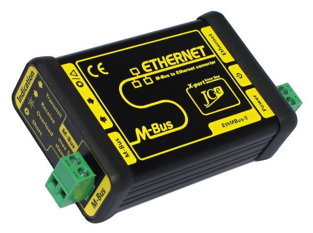
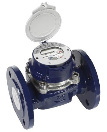
Last week, a request came up – to get a communication with the Sensus MeiStream 150 industrial flowmeter running. The flowmeter was equipped with the HRI-Mei data interface (specifically of type HRI-Mei B4/100L/500ms/40-125/50°C) communicating with the M-Bus protocol. To connect to the D2000 we used M-Bus/Ethernet converter made by Juraj Čaplický Elektronika - EthBus-5. (http://www.prevodniky.sk/product-EthMBus-5.html). This article describes the experience of running the communication in this configuration.
Components and Configuration
The customer bought an EthMBus-5 converter that is connected both to the M-Bus and the Ethernet network. This device supports communication with up to five M-Bus devices and has interesting communication capabilities:
- Transparent Gateway Mode: supports communication in UDP mode, TCP mode (both server and client) or in virtual COM port mode. In these modes, it functions as a classical converter, i.e., forwarding the requests received from the parent system to the M-Bus bus, listening to the answers and forwarding them up.
- Smart M-Bus Application Mode: it is capable of independent communication on the M-Bus bus, while processing the measured data and providing it in several formats:
o a web table
o xml, csv
o communication by M-Bus protocol (in UDP or server/client TCP mode)
o by email
o saving to an FTP server
About M-Bus Protocol
The M-Bus protocol is a European standard (EN 13757-2 physical and link layer, EN 13757-3 application layer) for reading data from gas, electricity and other flowmeters. On the M-Bus bus, there can be one master and up to 250 slave devices (meters) connected in parallel.
Physically, the M-Bus interface is a two-wire bus that, in addition to data transfer, can also provide power supply to slave devices. Therefore, logical 1 (in the direction from master to slave devices) is represented by voltage + 36V and logical 0 is represented by voltage + 24V. Slave devices respond by modulating current consumption - logical 1 is a constant current up to 1.5 mA, logical 0 is a current increased by 11-20 mA.
The current version of the M-Bus protocol is 4.8 and it is freely available at http://www.m-bus.com/mbusdoc/default.php. Master begins the communication with the SEND_NKE request (communication initialization) to the broadcast address 255 (an alternative in the D2000, which is configurable in line parameters, is to send the SEND_NKE request always to a particular station). An optional SND_UD (Send User Data) request follows – it is a command to change the communication speed (standard M-Bus speed is 300 baud, it is possible to change speed upto 38400 baud). Next - again, optionally, depending on the station parameters setting - the SND_UD application reset request is sent.
The device responds to these requests (unless it is a broadcast) with a single character confirmation - 0xE5. Finally, the master sends the REQ_UD2 request to receive class 2 user data. The response is data with the structure defined by the M-Bus protocol and an indication whether more data is available.
The answer may be fixed or variable.
Fixed response is simpler and includes the following fields:
- Identification No. - a 4-byte serial number (BCD encoding)
- Access No. –a number of accesses to a device (incremented by every reading, binary encoding)
- Status – various status information
- Medium /Unit – 2-byte code indicating the medium and units for the counter 1 and 2
- Counter 1 - a 4-byte value of counter 1 (BCD/ binary encoding by Status field)
- Counter 2 - a 4-byte value of counter 2 (BCD/ binary encoding by Status field)
The variable response includes a fixed header and variable data blocks.
Fixed header includes fields:
- Identification No. - a 4-byte customer number (BCD encoding)
- Manufacturer - a 2-byte number encoding three capital letters forming the manufacturer's code
- Version - a 1-byte number indicating the generation or version of the meter
- Medium - a 1-byte number indicating the measured medium
- Access No. - a number of accesses to a device (incremented by every reading, binary encoding)
- Status - various status information
- Signature - reserved for future use, so far 0 value
The variable data blocks contain information about the encoding, length and type of data as well as the data itself. One variable block can have a length of up to 240 bytes so that the total length of the data does not exceed 255 bytes.
The variable data block also contains information whether it is the last block or more data will follow (in which case it is necessary to send a new REQ_UD2 request). If the master does not want to read another data block, it can start a new communication cycle by sending SEND_NKE request.
How about converter?
The EthMBus-5 converter was first configured via the web interface in Smart M-Bus Application Mode. In this mode, it was able to read the flowmeter independently, so we verified that the connection to the M-Bus bus was OK.
The problem arose when we configured the communication in D2000 application via the TCP/IP-UDP link. The communication did not start – the restart of the KOM process as well as and various parameter tweaking didn’t help either. What to do next?
Using the Wireshark tool, we verified that KOM sends UDP packets that go through the network interface of the communication computer and that no responses are coming. But why?
My colleague Roman tried to send the requests SND_NKE and REQ_UD2 using the Hercules freeware utility (www.HW-group.com), which can also work as a UDP client.
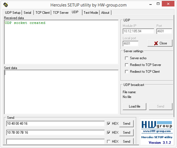
It was a surprise for us that Hercules got answers to the requests! After a moment of looking at the Wireshark logs, we also understood the reason. Hercules sent UDP packets from the configured port (4601) and received the answers on that port. The D2000 KOM uses a random port to send UDP packets and receives the answer on the configured port. This behaviour is compatible with Moxa NPort converters (they receive packets from any port, allowing only packets from configured IP addresses), but EthMBus-5 has more stringent constraints. What now?
Easier than rewriting the logic of the TCP/IP-UDP line was to support TCP mode of converter, i.e. communication through a TCP/IP-TCP line. Modification of both the KOM process and the CNF tool took about 2 hours, including incorporating the changes into the supported version 9.2.34, and after that, we established the communication.
An alternative would be to configure the converter into the Virtual COM Port Mode and use the serial line on the D2000 side, but my experience is that the best COM driver is none (I have already experienced Moxa virtual ports that have stopped working after a long time - perhaps a driver error).
The information about the difference in behaviour between the EthMBus-5 converter and the Moxa N-Port converters was also passed on to Mr. Čaplický, who promised that the future firmware version will also support the behaviour compatible with the N-Port converters.
Value identification and various optimizations
The D2000 help contains a useful information that after activating the FULL_DEBUG parameter it is possible to obtain information about unknown device. So we have done that and here are the logs:
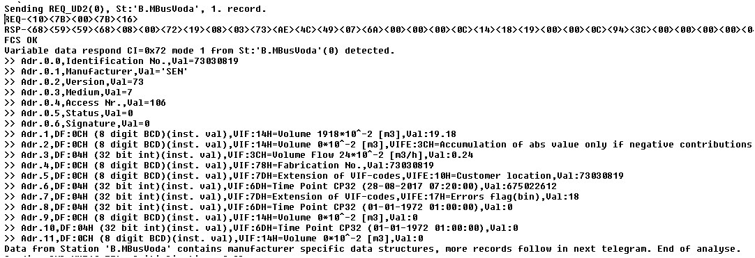
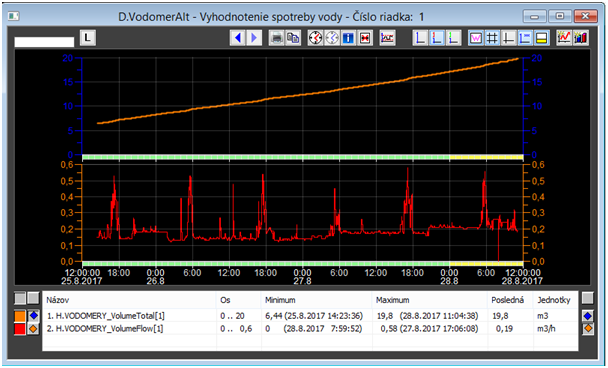
The figure shows that the Sensus meter sends variable data with the header (manufacturer's code 'SEN'). At the same time, we can see that interesting data is at address 1 (total volume 19.18 m3) and address 3 (flow 0.24 m3/hour).
From the water meter we were able to read up to 11 blocks of variable data, but they did not contain any interesting information for us. Therefore, by setting the 'Accept following records' station parameter to value of 1, we limited the reading of the data only to the relevant block 1 (which cut down the reading cycle approximately ten times). Subsequently, we reduced the time parameters - a delay after SND_NKE from 8 seconds to 0.5 seconds and a delay before sending REQ_UD2 from 4 seconds to 0.5 seconds. This way we got to approximately 0.5-second reading cycle (at 300 baud rate).

Conclusion
Communication with the Sensus MeiStream 150 is operational since Friday and the data goes into the MES system based on the D2000 real-time application server. During the debugging of the communication, we extended the implementation of the M-Bus protocol to support the TCP/IP-TCP line. This support will be available in all patches of D2000 KOM process in version 9.2.34 and later.