
In this blog post, we are once again bringing you a fresh translation of an older Slovak text. This one was written in 2017, but is still just as relevant. Read it and learn more about the HART protocol and how it can be supported using the HART/Modbus converter.
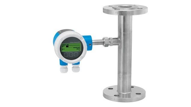
As soon as I posted the first part of the article on the Modbus communication protocol on the blog on Monday morning and planned the publication of the second (already written) part in a week, a colleague came up with the idea that the customer needed to establish communication with the Endress+Hauser Proline t-mass A 150 flow meter. Moreover, that it communicates via HART protocol and there is some HART/Modbus converter. This article describes the experience with initiating communication in this configuration.
Components and configuration
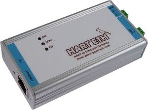
The customer had a HART-to-ModbusTCP converter (HART ETH) from Papouch company (Papouch means Parrot in Czech language). On one side it was connected to the Ethernet network (installation, configuration, and setting of the IP address was realized by the customer), on the other side by the 4-20 mA current loop to the E+H flow meter.
About the HART protocol
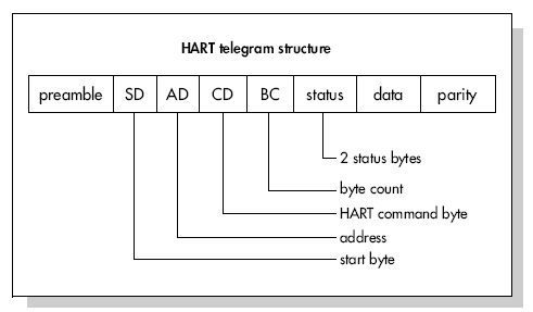
HART (Highway Addressable Remote Transducer) is a digital protocol that uses an existing 4-20mA current loop to transmit digital data. Digital data is modulated with an amplitude of 0.5 mA using frequency shift keyed (FSK) modulation. Binary zero corresponds to 2200 Hz, binary one to 1200 Hz. Devices that only support reading the analog 4-20mA signal perceive HART communication as a minor interference.
The HART protocol was developed by Rosemount in the 1980s as a proprietary protocol for their intelligent devices. In 1986, it became an open protocol in version 2.1. Currently, most devices support version 5 (standard from 1989), fewer devices support version 6 (the year 2001 - support for long identifiers), and the current version 7 (the year 2007 - Wireless HART).
As of March 2011, all new devices must support protocol version 6 or 7 and be registered with the HART Communications Foundation (http://www.hartcomm2.org).
According to the documentation, the flow meter we need to communicate with supports protocol version 6.
How to work with the Parrot?
The HART ETH converter from the Papouch company works in an interesting way:
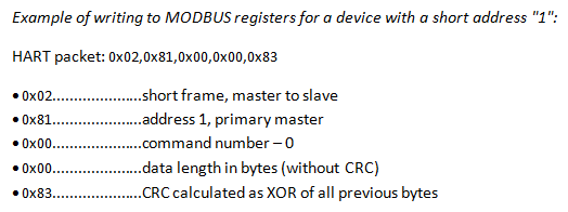
- Using the MODBUS protocol, it is possible to write to the converter a HART packet that we want to send (to the registers from address 52). Writing can be realized by one or more Modbus write operations with the function 16 - Write Multiple Registers. According to the manufacturer's documentation, the packet starts with a start byte and thus does not contain an introductory preamble (3 or more characters 0xFF synchronizing the subscriber's signal).
- Subsequently, writing the value 0x0100 to register 50 of the converter starts HART communication. The converter sends a HART packet and waits for a response.
- It is necessary to read register 50 until the value changes from 0x0100 to 0x0200 (successful HART communication) or to 0x0000 (error/timeout).
- If the communication was successful, the HART response of the device can be read from the registers at address 308 and higher. The answer must then be parsed and interpreted.
How to work with HART?
So we already know how to convince the Parrot to send and receive a HART packet, but we still have no idea what such a packet looks like and what HART actually knows. I would like to commend the gentlemen (or ladies?) from the Papouch company - their instructions contain examples for two important HART commands:
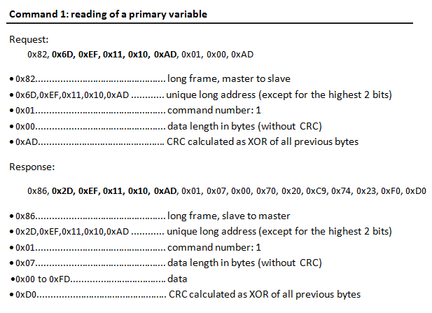
HART command 0 – reading of a unique identifier - is a simple 5-character command whose only parameter is a short device identifier (0-15). The device response includes, but is not limited to, information about the supported version of the HART protocol, Manufacturer ID, Manufacturer Device Type, and three-byte Device Identification Number. The combination of manufacturer ID + device type + device ID creates a 5-byte Unique Identifier, which is used in all other commands in protocol version 5 and higher. The use of a unique identifier protects against communication errors from the wrong device (which can occur when connecting and chaining HART loops).
HART command 1 – reading of primary variable - reads one value (a real number) from the device. To address the device, it is necessary to use the unique identifier obtained in the previous point. Here, Papouch gives an example of a command and a response too, but they no longer discuss the internal structure of a 7-byte response. Apparently, they assume that the reader has this information available - which was not my case. Hence some of the time was spent on finding out the structure of the data (by reading unofficial sources and analyzing the data received from the device).
In the end, a combination of two information sources helped. The first was a document with HART commands, from which is the following table:
|
Command number and function |
Data in command |
Data in reply |
(type) |
|||
|
0 |
Read unique identifier |
|
none |
Byte 0 Byte 1 Byte 2 Byte 3 Byte 4 Byte 5 Byte 6 Byte 7 Byte 8 Byte 9-11 Byte 12 ** Byte 13 ** Byte 14 ** Byte 15 ** |
"254" (expansion) manufacturer identification code manufacturer's device type code number of preambles required universal command revision device-specific command revision software revision hardware revision device function flags* device ID number common-practice command revision common tables revision data link revision device family code |
(H) (B) |
|
1 |
Read primary variable |
|
none |
Byte 0 Byte 1-4 |
PV units code primary variable |
(F) |
The second source was another document stating that the response always contained a double-byte Response code at the beginning. Thus the final form of the response to command 1 is this:

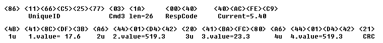
At the end, we did not use HART command 1 for the customer, but HART command 3, which allows reading of 4 values as well as value of the current in the current loop. The command looks practically the same as command 1 (it differs only in the byte indicating the command number), however, the answer is more extensive:
|
Command number and function |
Data in command |
Data in reply |
(type) |
|||
|
3 |
Read current and four (predefined) dynamic
variables |
|
none |
Byte 0-3 Byte 4 Byte 5-8 Byte 9 Byte 10-13 Byte 14 Byte 15-18 Byte 19 Byte 20-23 |
current (mA) PV units code primary variable SV units code secondary variable TV units code third variable FV units code fourth variable |
(F) (F) (F) (F) (F) |
This command has a similar response parsing as HART command 1:
How to work with D2000?
One line (of TCP/IP type) and three stations were used to communicate with the HART ETH converter. Why as many as three?
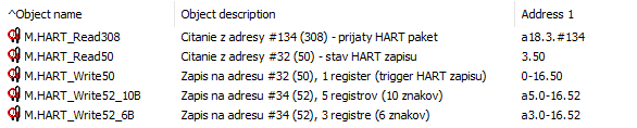
The first station (B.HART_ETH_Write) contains three output measured points for writing commands 0, 3, and starting communication - in the figure below, M.HART_Write52_6B, M.HART_Write52_10B, and M.HART_Write50. The first two points are of text type and differ only in the length of the written string - 6 bytes for command 0, 10 bytes for command 3 (the alternative would be to create 5 single-register variables and write to them, but one write to a text measured point is a more elegant solution). The third point is of integer type and writing the value 0x0100 to it will cause the start of HART communication and sending a request from the HART ETH converter to the HART device.
The second station (B.HART_ETH_ReadStatus) contains an M.HART_Read50 point for determining whether HART communication has already ended and with what result. By default, the station has the off state (StOff) and is switched on only after the communication has started. As soon as the read value of the point M.HART_Read5 is equal to 0x0200 (OK) or 0x0000 (error/timeout), the station is switched off again so that the periodic reading of the point does not slow down the other communication.
The third station (B.HART_ETH_ReadReplyValue) contains an M.HART_Read308 point to read the HART response from the converter. This text measured point has a specified length of 18 registers (36 characters), which is sufficient enough to read the response to both HART command 0 and command 3 (see Figure 10). The station, like the other station, is always switched off and only switches on to retrieve the response.
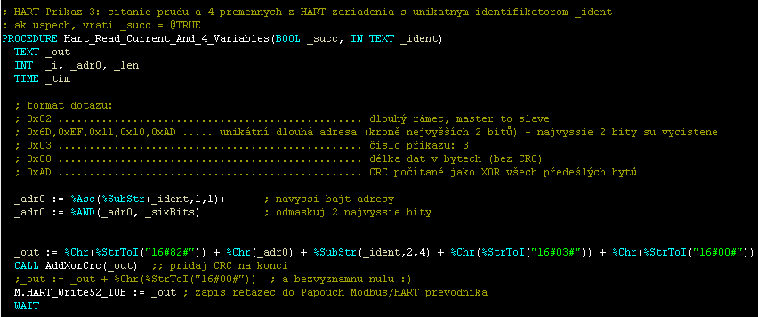
Composing HART commands and parsing HART responses was done in an ESL script. During the implementation, I found that I needed the %XOR function to implement the CRC as well as the %B4ToReal32 function, which converts four bytes to a 32-bit real number. This was an advantage when using D2000 real-time software technology - on Monday evening I asked the head of development for the %XOR function and the next day at a quarter to nine I had patches available for version 11! The implementation of the %B4ToReal32 function was more complicated (the request was made on Tuesday afternoon and the patches were not ready "until" on Wednesday 10:10), but it is necessary to recognize the higher complexity of the implementation also due to the need to test for invalid inputs. In addition, there was an intensive discussion during the development about the name of the required function :)
Boris, thanks .. and a question for the reader - try to think about how long it would take to meet a similar requirement when using some competing software?
Conclusion
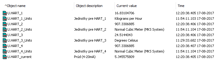
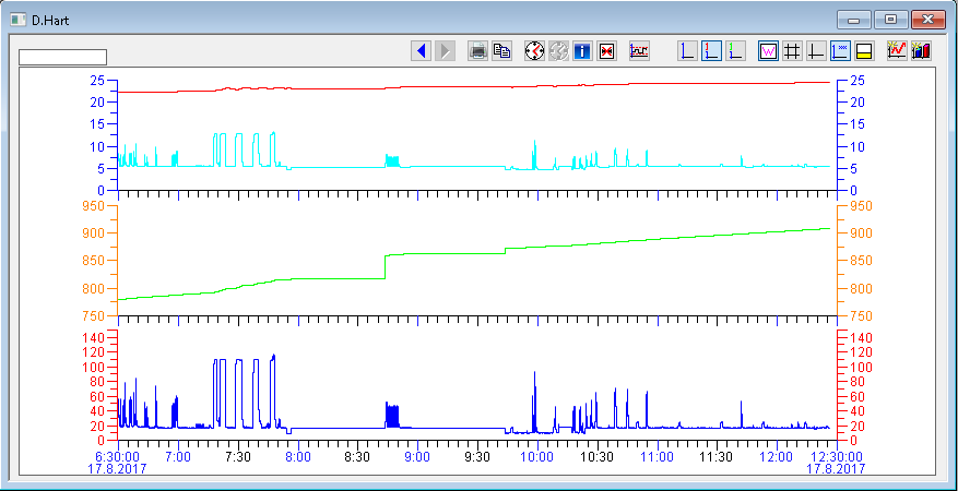
Communication with the E+H flow meter has been functional and trouble-free since yesterday (including resistance to KOM process restarts). Based on the information obtained from Mr. Google, we also added the identification of the code of units of measured quantities.
This real-life example shows how popular and widespread the Modbus protocol is and for what it can be used in practice. Of course, it is dependent on the specific application server (and its communication or scripting subsystem) whether and with what amount of work it can cope with such an unusual use of the popular and widespread protocol.
Ing. Peter Humaj, www.ipesoft.com
