
To enrich our blog content, we bring you freshly translated blog posts by Peter Humaj. The blog posts were originally written in the Slovak language in 2017, 2018 and 2019. They focus on the communication protocols used in the world of industrial automation and SCADA and MES systems. Even though they were written a couple of years ago, the information provided is just as relevant today.
The introduction to Modbus
Modbus is one of the simplest communication protocols (and most likely because of that it is widely used). Let's look at its features .. and the problems with implementation in practice.
The Modbus protocol was designed in 1979 at Modicon to communicate with their PLC as a simple and robust master-slave serial protocol. Currently, the Modbus organization is responsible for its development and the actual version of the standard is V1.1b3.
Modbus recognizes only 4 types of objects:
· Coils (1-bit binary states)
· Discrete Inputs (1-bit read-only binary inputs)
· Holding register (16-bit analog states)
· Input registers (16-bit read-only analog inputs)
Each object type is addressed by a 16-bit (0-65535) address. The data is 16-bit, sent as big-endian (first higher byte, then lower). In the case of binary, sixteen values of consecutive objects are sent in 16 bits (e.g. with address 16, 17, 18..31)
The protocol has defined functions for reading each object type and writing non-read-only types:
· Coils: Read Coils (1), Write Single Coil (5)
· Discrete Inputs: Read Discrete Inputs(2)
· Holding register: Read Holding Registers(3), Write Single Register(6)
· Input registers: Read Input Registers (4)
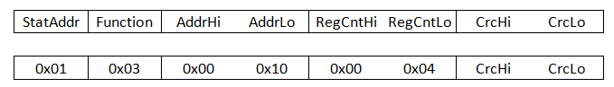
When reading, the address of the starting object and the number of the read objects (1-2000 for binary, 1-125 for analog) are specified so that the total length of the returned data does not exceed 250 bytes. Additionally, there is a Write Multiple Registers function (16) for writing multiple registers at once.
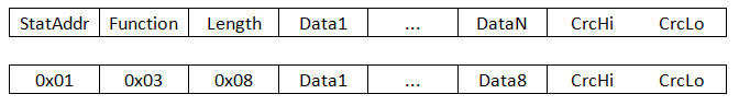
The read or write response is a data packet or error code with an exception number describing why the read or write failed. The data packet contains information about the size of the data in bytes.
Furthermore, the protocol defines specialties, e.g. Read/Write File Record, and various diagnostics, but the common implementations do not include them. Henceforth, the client periodically queries the values of all objects of different types (the more it can put into one request, the shorter the total reading takes) and the server sends responses. No support for on-change data such as e.g. IEC 60870-5-101, IEC 60870-5-104, asynchronous mode OPC, TG809, and other protocols. There is no support for flags (validity, weak, etc.) as well as no support for timestamps or history reading.
The protocol uses single-byte addressing of the slave device (by default 1-247, higher addresses are reserved), address 0 is a broadcast. Thus, there can be several devices on a serial line, each of which must have a unique address.
There are RTU variants of the protocol (binary encoding) and ASCII variant (BCD encoding, so it is 'readable' in the text listing, but twice as slow, as each byte is coded by the BCD with two bytes).
An RTU variant for TCP connections (TCP port 502) exists – there are even two:
· "MODBUS TCP" does not use a checksum (CRC) and relies on TCP mechanisms
· "MODBUS over TCP" uses the checksum in the same way as the serial variant
That is about the theory. What complications can arise in practice?
A very straightforward answer - all of them :)
The first complication: addressing
Due to some devices, 2 addressing modes have been introduced:
· "MODBUS PDU" - data is addressed from 0 to 65535
· "MODBUS data Model" - data is addressed from 1 to 65536 (address 9 is used in the protocol when reading the measured point with address 10)
The address of the measured point can be entered in the D2000 CNF configuration tool in decimal or hexadecimal form using a grid (#), e.g. #50CE. This simplifies address configuration and control if the device-specific documentation uses a hexadecimal form.
D2000 KOM tries to send requests to read as many registers as possible (which can be limited by the parameter "Max. Registers"). However, some devices return errors if the request also contains addresses that do not contain data. E.g. if the request contains the address of the starting object 100 and the number of the read objects is 4 and the device has defined objects for the addresses 100, 101, 103 (but not 102), then it may return an error. For this case, there is a protocol parameter "Skip Unconfigured", which causes the KOM process not to request values for addresses at which it does not have defined measured points. After activating the "Skip Unconfigured" parameter, the above request would be divided into two: address 100, length 2 (i.e. addresses 100 and 101) and address 103, length 1.
The second complication: types of variables and Endians
Since Modbus only defines binary and 16-bit unsigned variables (sent as big-endian, i.e. higher byte first, then lower byte), various implementations have defined the remainder as needed by reinterpreting the data:
· 8-bit variables can be in either the upper or lower byte of the 16-bit register. They can be unsigned/signed.
· 16-bit variables can be unsigned/signed integers sent as little/big-endian
· 32-bit variables were created by merging two registers in a row:
- unsigned/signed integers can be sent as little/big-endian
- real numbers (float) can be sent as little/big-endian
· 64-bit variables were created by merging four registers in a row:
- unsigned/signed integers can be sent as little/big-endian
- real numbers (float) can be sent as little/big-endian
· text variables were created by merging several registers in a row:
- one register can contain one character (16-bit UTF16)
- one register can contain two characters (8-bit ASCII) - e.g. some electricity meters ABB A41..44 (ABB 4x)
· Another specialty is the Endress + Hauser RMS62 calorimeter. It implements the state of a real value by a separate register located before the other two registers, which contain a 32-bit float in a big-endian format. The status contains values corresponding to e.g. Invalid value, Valid value, Overflow/Underflow warning, Saturated steam alarm, and others specific to a particular calorimeter.
Endians get even more complicated if more than 1 register is sent. For example, let's have a 32-bit number (i.e. occupying 2 registers) with a hexadecimal notation of 0x44332211. If sent as a big-endian, bytes 44, 33, 22, 11 are sent sequentially. But there are several little-endian options:
· 11, 22, 33, 44 – bytes are sent from lowest byte to highest
· 22, 11, 44, 33 - first lower register (lower 2 bytes), then upper, but within the register the higher byte is sent first
· 33, 44, 11, 22 - first upper register, then lower, but within the register the lower byte is sent first
In addition, integer variables can be coded in binary (256 values per byte) or BCD (100 values per byte).
All the above types are supported in the addressing of measured points in the D2000 in the Modbus IDA Client protocol.

The third complication: the size of the registers
Although the standard defines that the register has 16 bits, there are implementations that do not respect it:
· 1 register has 1 byte – in the D2000 it is possible to activate byte mode with the “Byte Mode” protocol parameter.
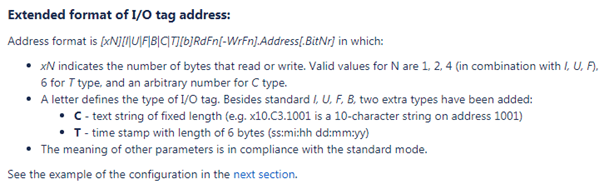
· 1 register has a variable number of bytes (1,2,4) - depending on the configuration and type of object. In the D2000, it is possible to activate the variable mode with the “Variable Mode” parameter protocol and to specify the register size in the configuration of the measured point. We encountered such wild behavior at the FloBoss 103 flow meter from Emerson. Because of it, other special types are also supported in D2000, e.g. registers for text strings of 10, 20 or 30 bytes in length or a 6-byte timestamp (ss:mi:hh dd/mm/yy).
The fourth complication: Write Multiple Registers
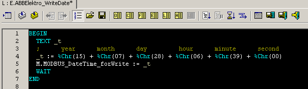
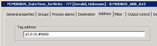
There are applications that require multiple registers to be written at once by the Write Multiple Registers function (16). An example is the already mentioned ABB A4x series of electricity meters, which supports time and date synchronization by writing to registers. This must be done in one write by the Write Multiple Registers function (16), which writes 3 registers at once, i.e 6 bytes.
Something similar can be configured in the D2000 in two ways.
The first method uses the write to a measured point configured as a text string with a length of 3 registers - 6 characters (8-bit). In the script, it is possible to compose a string according to the current date and time and then write it.
The second method uses the so-called delayed writing. If the output measured point in the D2000 has the Write Multiple Registers function (16) configured followed by the ‘d’ flag, the write is delayed and is executed only when a write request is received for a point that does not have a delayed write configured. Subsequently, the KOM process tries to perform all accumulated entries with a single Write Multiple Registers. This method is advantageous for notations that do not work with byte and text-oriented values (such as time and date above) but e.g. with 16/32/64-bit integers or 32/64 float values.
The fifth complication: application specialties
The most prominent example of how Modbus can be used to transmit ‘almost everything’ is the aforementioned ABB A4x meters. In addition to the aforementioned time notation, the following features are supported:
· reading of historical data
· reading of previous values (daily, weekly or monthly)
· reading of event logs
· profile reading and profile configuration (8 channels with a period from one minute to 24 hours)
· configuration of previous values, profiles, alarms, inputs/outputs, and tariffs
In a specific application, we implemented reading of profiles (historical values), reading and writing of their configuration, reading and writing of alarm configuration, and reading of event logs (information about alarms and events that occurred and the electrometer keeps them in memory).
All the mentioned specialties were implemented at the application level, in the ESL script. They used the possibility to stop and start communication with a particular station from the script (and wait for the values of input measured points to be read) as well as the possibility to dynamically change the address of the measured point from the script (and wait for the value to be read again).
Several stations in D2000 were created for one electricity meter. One was used for regular reading of values, the others were switched off by default and, if necessary, were used for the above-mentioned application functionality. E.g. three stations were needed to read the profiles - one contained points for channel selection (OBIS object code) and time and date settings for the read profile, through the other station the profile information was subsequently read (interval, scale, whether it is unsigned or signed data) and the third one was for the historical values themselves.
The sixth complication: GSM networks
The complication concerns the GSM networks and their time behavior. What's the problem? On a simple serial line, the answer either arrives (at a defined time) or not. On the GSM network - in the configuration that the D2000 KOM sent requests via the GSM network to the Moxa OnCell modem, behind which the devices were on the serial line - a problem was encountered: the response to the request sometimes came with such a delay that the KOM process sent a request again. So it processed the answer to the second request as an answer to the first one, everything was fine. It then sent a request to read other data and received a response to the second request. Since the response contains only the length of the data, but not their address, the data have been intermixed (assigned to wrong measured points).
What about that? One solution is to set "large enough" time constants to receive a response to cover GSM network delays. The second tool is the "Check Receive Length" parameter, which compares the length of the data in the response with the length that was sent in the request. If they do not match, the packet is dropped. The parameter is supported for standard and byte mode, not yet for variable mode.
D2000 and the Modbus server
The D2000 KOM has a server-side of the Modbus protocol implemented, so it can also serve as a Modbus server. It supports all standard read and write functions and can publish measured points as 16/32-bit integer values (i.e. 1 and 2-register) and 32-bit real values (2-register), optionally in little/big-endian format. Unlike the client-side of the Modbus protocol, there was never a need to implement things like variable or byte mode, text variables, etc. - probably because in case of need for the D2000 communication with the superior system there are several more modern protocols implemented in the D2000 (OPC server, IEC104 server, IEC101 server, ICCP server), which are change-oriented, support timestamps, authentication, and other options. Therefore, the server part of the Modbus protocol is relatively simple and it does not make sense to write a separate article about it.
Conclusion
The aim of this article was to demonstrate concrete examples of what different ‘dialects’ can arise in practice from a simple Modbus protocol. The list of exceptions and specialties is certainly not complete - the mentioned ones are those which we encountered in practice. As the saying goes, the theory is gray, the tree of practice is green .. and sometimes such strange leaves grow on it, that the layman is amazed and the expert is surprised...
