
In the latest blog series, we are bringing you freshly translated posts by Peter Humaj. This text was originally written in 2019. It focuses on establishing communication using the Modbus protocol. The information provided by the blog post is just as relevant, as it was in 2019.
Today we will try to establish communication using one of the most used communication protocols - Modbus.
In practice, we needed to communicate with the Honeywell UDC1700 controller. It is a compact PID controller on a DIN rail, which is optionally equipped with a module for Modbus communication via RS-485. It supports a binary variant of the Modbus RTU protocol as well as a Modbus ASCII text variant.
So - how to communicate with it using the D2000?
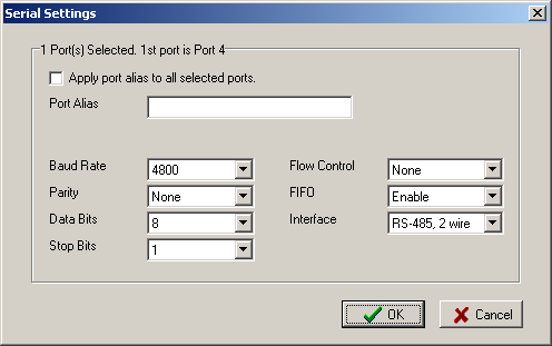
The documentation states that by default the UDC1700 communicates at 4800 baud, without parity, using the Modbus RTU protocol and its default Modbus address is 1.
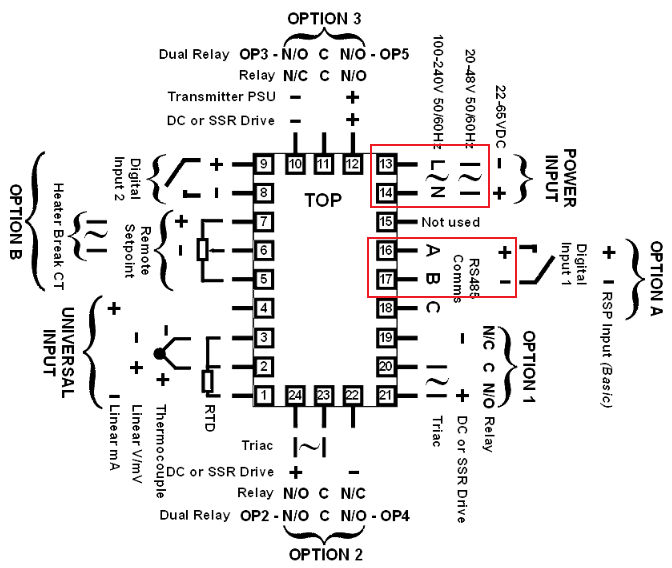
According to the label directly on the UDC1700, the data connectors are no. 16 (+) and 17 (-). Power is connectors 13 (phase) and 14 (ground).
Since I don't have an RS-485 port on my computer, I used a proven RS-485 to Ethernet converter - Moxa NPort - more specifically the 5450I model with four universal ports that can be configured in RS-232, RS-422 or RS-485 mode.
According to the instructions for NPort, wires no. 4 and 5 are used for 2-wire RS-485 on the DB9 connector.
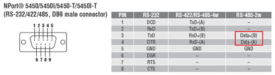
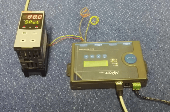
So I connected the power supply (220 V) to terminals 13 and 14 of the UDC1700 controller and connected terminals 16 and 17 to pins 3 and 4 of Moxa NPort. Subsequently, I connected NPort to the local network.
I then connected to NPort with the NPort Admin tool. Its IP address 172.16.22.223 is shown on the built-in display. I will use port 4 to communicate with the UDC1700. Since it does not have the required parameters, we are going to modify them.
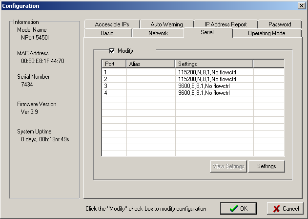
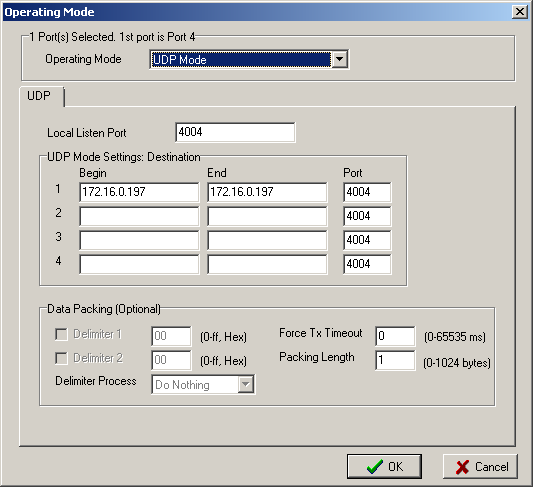
After checking the Modify checkbox, selecting port 4 and clicking on Settings, a configuration dialog will open in which I have set the relevant parameters:
On the Operating Mode tab, set the mode for each serial port. We can use the following modes when communicating with the D2000:
- Real COM Mode, in which a virtual serial port is created on the computer (using Moxa drivers)
- TCP Server Mode, in which NPort acts as a TCP server
- UDP Mode, in which NPort receives and transmits UDP packets
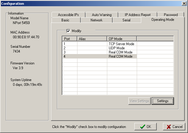
In practice, using the third mode works best for us. Why? The virtual serial port can get stuck (possible problems with NPort drivers) and in TCP Server Mode, timeouts caused by the TCP layer can occur during network outages. We have successfully used UDP mode on all platforms where D2000 has been ported (Windows, OpenVMS, HP-UX, Linux, Raspberry PI). Hence we'll use it here, too.
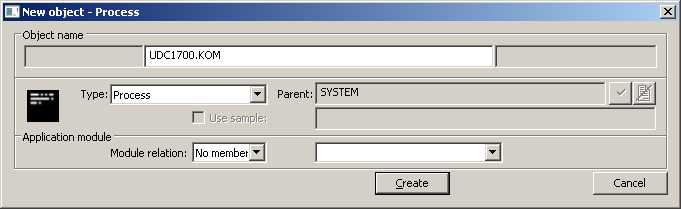
This completes the configuration of both the controller and the Moxa, and now I can focus on the configuration of the D2000. Firstly, I created a new communication process UDC1700.KOM. I could use the standard SELF.KOM, but on a test application that is used for different purposes, I try to keep order and create different communications on different KOM processes. Then I run the process I need. In our case, I run it manually from the command line
kom.exe /WUDC1700
The /W parameter is used to specify the process name.
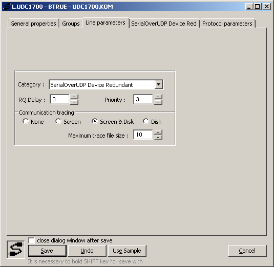
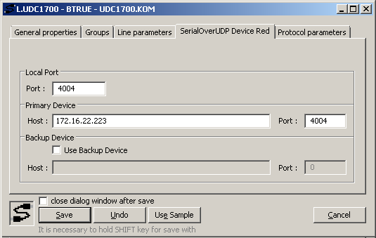
Then I will create a line. It will be called L.UDC1700 and as a parent, I will specify the UDC1700.KOM process. Within the line parameters, I select the line category - SerialOverUDP Device Redundant and turn on logging to the screen and disk.
On the tab of parameters specific for the SerialOverUDP Device Redundant line, I will set the IP address of the NPort and the ports used for UDP communication - I will set the local and remote port to 4004 (which are the values from Figure 6). By default, I use the same ports on the D2000 and NPort side so as not to be mistaken :-)
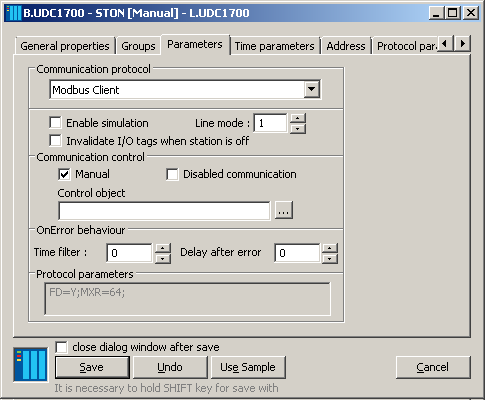
The creation of the station follows. Select the L.UDC1700 line as a parent and select the Modbus Client protocol in the Parameters tab:
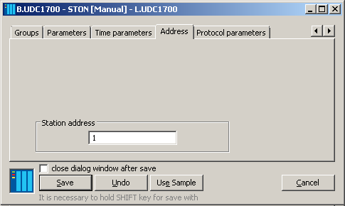
As next, enter the station address - according to the UDC1700 documentation, the default address is 1.
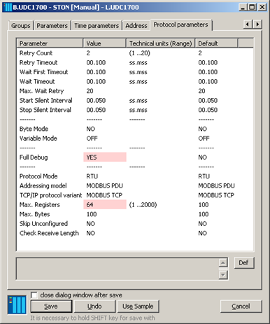
In the protocol parameters on the last tab, I turned on complete debug messages and set the Max. Registers parameter to 64. Why? Because the UDC1700 documentation says that a maximum of 64 words (registers) can be read in one request: The maximum number of words that can be read is 64.
If it was necessary to optimize and speed up communication (e.g. with multiple devices connected to the same line), I would start by modifying the time parameters (Wait First Timeout, Wait Timeout).
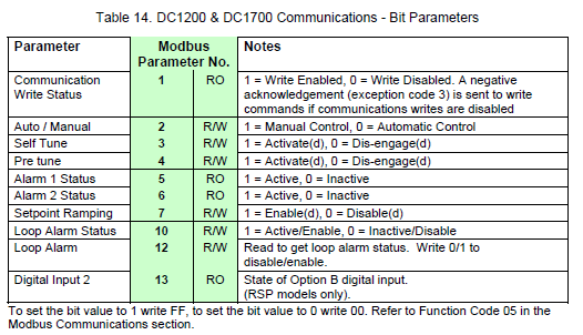
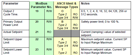
The last point is to configure the measured points (in D2000, we call them the I/O tags). All measured points will have the B.UDC1700 station as a parent. The controller documentation contains a table with a list of bit variables:
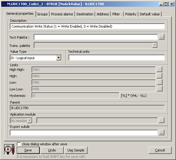
Hence, I will create a measured point named M.UDC1700_Coils1_1 and the value type Di - Logical input.
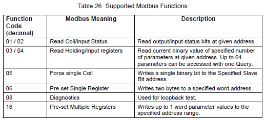
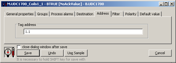
In the Address tab, I will set the address according to the documentation for the Modbus protocol. The address is in the functionRead.address format, where the functionRead is the Modbus read function. What function does the UDC1700 support? The answer is in the documentation:
Thence, our address will be 1.1 - the first number indicates the read function 1, the second the address of the Communication Write Status parameter from Figure 13.
Immediately after saving the measured point, it acquired the value BTRUE (which can be seen in the window header). What does it mean? The communication with the UDC1700 started on the first try and that the D2000 KOM does not need any restarts by default, but accepts the online configuration change.
As another point, I will try working with 16-bit registers - not only reading but writing as well.
I will create a measured point of type Ao - Analog output:
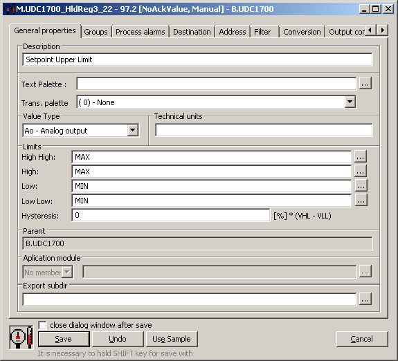
I get the parameter address again from the UDC1700 documentation - Setpoint Upper Limit has address 22.
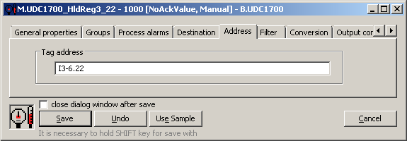
How to specify an address? If we only wanted to read, the address would be 3.22 (read function 3, address 22). If we want to write into it as well, it is necessary to specify the function for writing (according to Figure 16, it is function 6), so the address will be 3-6.22 (according to the convention functionRead-functionWrite.address).
According to our Modbus protocol documentation, it is possible to enter a value type before the function. The default type is a 16-bit integer (so address 3-6.22 means the same as I3-6.22). The question is - is it correct to interpret the value as signed (I) or unsigned (W)? The controller's documentation is silent about this, so we will use the sign interpretation, which is the default for Modbus.
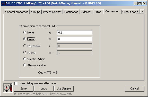
Again, after saving, the measured point came to life and its value is 1000. But, there is the value 100 on the controller display. And if I change it to 99.9 on the controller, the value in the D2000 is 999. What's the problem?
The answer is straightforward - in order to be able to set the parameter by one tenth and at the same time transfer its value exactly, it is multiplied by ten during the transfer. However, this information is not in the controller manual - or at least I did not find it.
Therefore, on the D2000 side, it is necessary to set the inverse conversion on the Conversion tab.
The last point is to test writing. It can be done from HI, but also directly from the Cnf configuration tool. So, from the context menu of the measured point, select the Value watch option and change the value from 100 to 88 in the window:
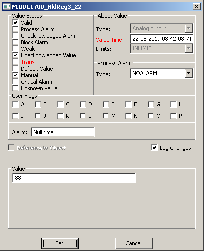
After clicking on the Set button, the Transient status flag was set for a fraction of a second (the value is being changed) and after successful communication to the controller, the flag was cleared (and the value time was also updated).
If the parameter Setpoint Upper Limit was displayed on the display of the controller, the change can be seen immediately after writing:
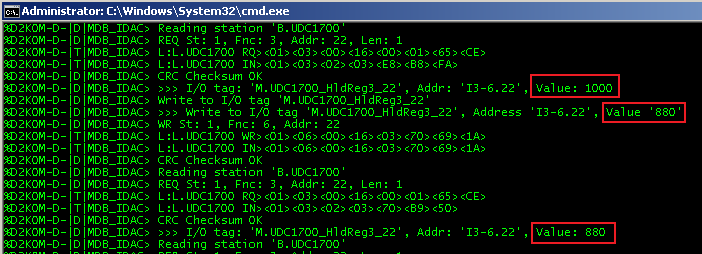
The following screenshot shows the listings of the D2000 KOM process. The first highlighted value (1000) comes from the reading. Then a value is written (880) and read again (880). The displayed values are therefore "raw" values from the protocol, before applying the linear conversion.
The purpose of this blog was to show what is needed to establish the Modbus communication in the D2000 system. At the same time, I wanted to illustrate that if everything is well connected (and if don’t make mistakes during the configuration), it is a simple and logical process.
Ing. Peter Humaj
