
First part of this blog described the industrial robot Fanuc LR-Mate 200iD with the R30iBPlus Mate controller and its communication options. We borrowed this robot from our OEM partner who needed to design an optimal way of data exchanging with the D2000 real-time application server.
At the end of the blog I mentioned the communication options for Fanuc LR-Mate 200iD. From the listed options, the usage of Modbus TCP and Ethernet/IP protocols for communication seems to be the faster, the communication via User Socket Messaging (programming your own protocol built on TCP/IP) is the most cost-effective.
Which option did we recommend as optimal?
The answer is – none of them. Why? The listed communication options do not cover all communication possibilities of Fanuc robots.
There is a proprietary protocol SRTP (Service Request Transport Protocol). As stated on Wikipedia, this protocol was developed by GE Fanuc Intelligent Platforms (at present it is a part of GE Automation & Controls), whose previous name was GE Fanuc. It was established in 1986 as a joint venture between the two companies. GE Fanuc first had developed the proprietary serial communication protocol SNP (Series 90 Protocol), which was used for communication with their PLC Series 90. Later, after the modernization of PLC and embedding the Ethernet ports, GE Fanuc had modified this protocol, which resulted in new variant built on TCP protocol. Its name was SRTP.
Wikipedia also states that this protocol is used to communicate with almost all devices of industrial automation that are equipped with Ethernet port produced by GE.
SRTP protocol is proprietary protocol and you can find only fragments of unofficial information on the web. Partially a description of SNP protocol, which SRTP is based on, can help and partially information on various forums.
Read and write memory
It is a common request-response protocol that is similar to Modbus TCP. It offers various options but we were interested only in „read system memory“ and „write system memory“.
When specifying the read and write memory, first you have to define a memory type (Memory Area), then bit address of the first addressed element (number 1-65535) and finally the number of elements.
Some types of memory allow you to access the elements both bit by bit and by byte. We implemented a work with the following types of memory:
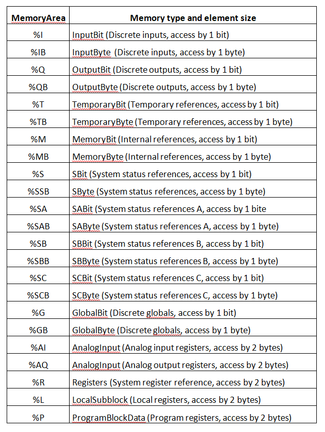
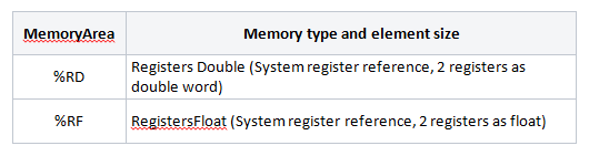
In addition to these native memory types, we supported memory type % IGNORE (I/O tag will be ignored - it is used to exclude I/O tag from the communication without the need to delete it) and two composite types that consider 2 consecutive registers as a 32-bit number (integer or floating point).
For each integer type we supported the interpretation as a signed and unsigned number.
Test findings
When testing against R30iBPlus Mate controller we found out that we can read the values from the memories of these types: %I, %IB, %Q, %QB, %M, %MB, %G, %GB, %AI, %AQ, %R (even %RD, %RF)
We verified the reading from memory type Registers (%R) – the read values were consistent to data that were displayed by teach pendant.
We have also implemented writing into above mentioned types of memory. When testing, we found out that although R30iBPlus Mate reports that the writing was successful, only the values of the Register memory changed. For other types of memory the follow-up reading returned the initial values. This may be related to the fact that the controller, with which we communicated, did not have embedded any input / output cards. We'll see how successful further testing will be at our OEM partner.
Other useful feature we have supported is configuring more elements to the items of structured variable in I/O tags with the configured Target column of structure. This feature of D2000 System allows – if it is supported in the particular protocol – loading the contiguous interval of elements into the column of structure variable using a single I/O tag. This saves both tags (customer's money as well) and time necessary for configuring a large number of elements.
We found the answer in the technical documentation. A manual with the long name FANUC Robot series R-J3/R-J3iB/R-30iA CONTROLLER CIMPLICITY HMI for Robots OPERATOR’S MANUAL (B-82604EN/01), describing the communication of robots with the visual system GE CIMPLICITY, contained exactly the information we have needed.
Many of the object types are directly mapped to specific memory types. For example, Robot Outputs are mapped to binary inputs (RO[1] to %I5001, RO[2] to %I5002 up to RO[8] to %I5002). Because these mappings are important, we also copied them into our documentation.
Registers of robot (R), position registers (PR) and current position (POS) are optionally available. What does it mean? Robot contains the system variable $SNPX_ASG (in fact, it is an array of structures), with which it is possible to map these object types into the memory of Register (%R) type. In addition to specifying the position, we have to configure whether the objects are mapped to one register (as 16-bit number with sign -% R) or to two registers (either as 32-bit number with sign -% RD, or as 32-bit real number - %RF). At the same time, we have to define a conversion multiplier - a constant by which the objects are multiplied during the conversion.
During the practical test, we tested the reading and writing of Robot Outputs (changes were also reflected in the audible click of the relay and the change of values on the Teach Pendant), reading and writing Position Registers (if they were displayed on the Teach Pendant, it was necessary to leave the display and re-enter to be recovered) and reading Current Position (the writing did not work, probably for security reasons).
Conclusion
As robots become an increasingly important part of industry - even within Industry 4.0 – the need of collect production and diagnostic information from them is growing as well. D2000 real-time application server with its features can comprehensively cover such functionality – from data collecting, through their automatic processing, evaluation, archiving and alarm signalizing to the creation of reports.
Ing. Peter Humaj, www.ipesoft.com
